As you may know I’ve been waiting on components to finish my “Color Preamp”. I thought that I’d have my output coupling capacitors by now, but I was mistaken. It seems that my parts supplier, after promising to get the parts right out to me, spent three days trying to find the parts in their warehouse, then sent me a refund. But I thought I’d outsmarted them.
This is what I did. When I ordered my volume potentiometer from another supplier, I added to that order a few generic 1.0µf axial film capacitors. That way (I thought) if the other parts didn’t get here in time, at least I’d be able to get the preamp up and running in another way.
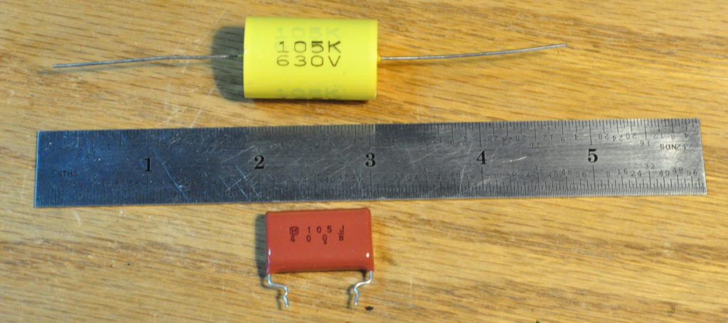
I was wrong. The backup capacitors did indeed show up with the potentiometer. But there’s a not so small problem. See if you can pick it out in the attached photo.
On the bottom is the original part I ordered but with the wrong lead formation. On the top is the comically large part that arrived from my other supplier. I really didn’t think they looked that large in the picture on their web page. They didn’t have a 400v part in stock but I thought that the 630v part couldn’t be too much larger. The axial part is 3/4″ (19mm) in diameter and almost 1-1/4″ (31mm) in length. I spent about 10 minutes trying to figure out how to fit these in the small chassis. There is just not enough space to fit them in. Maybe if I didn’t have the cathode follower buffer stages there might be room. But that end of the chassis is fairly cramped and I just can’t make it work with the layout I have.
So now I need to decide if I want to just solder some wires to the first parts I received and use them (I don’t consider this a particularly attractive solution), or to wait for yet another supplier to attempt to deliver the parts I really need. This was supposed to be the “quick” project and now it’s coming up on two full weeks since I drilled the chassis on February 3rd. And I still don’t have it fully wired. This may not seem like a long time, but it feels like this is the project that will never end.
On a more positive note, the output coupling capacitors are the last components for which I’m waiting. I received my dual 10kΩ audio taper potentiometer yesterday (with the comically large capacitors shown above). It is now installed in the chassis with a pointer knob attached. So from the outside, the unit looks complete.
I am hopeful that I can get this project working this week. There is one thing of which I am very sure. If I built another one of these (which I probably will), I will definitely be putting it in a chassis that’s much larger.
As always, questions and comments are welcome.
Update 16 February 2022: It looks like the proper parts are in the mail and should be delivered this coming Saturday. I decided that I wanted to use the proper parts instead of trying to do “make work” with what I have on hand.


It is amazing how something that seems only slightly larger than the part you are trying to substitute turns out to be a monstrous behemoth. Did the supplier have an on line data sheet that you could have used to verify dimensions? Many suppliers offer them. I frequently refer to them since in solid state PCB construction part size is critical.
A side note – I used to name my daily jobsite reports back to the main office “Tales of Woe” – sometimes they actually were.
Unfortunately these were purchased from a reseller and no data sheet was available. I’m not even sure who manufactured them. I am assuming it was some generic parts house in China. Clearly these were NOT IC (i.e. Cornell Dubilier)