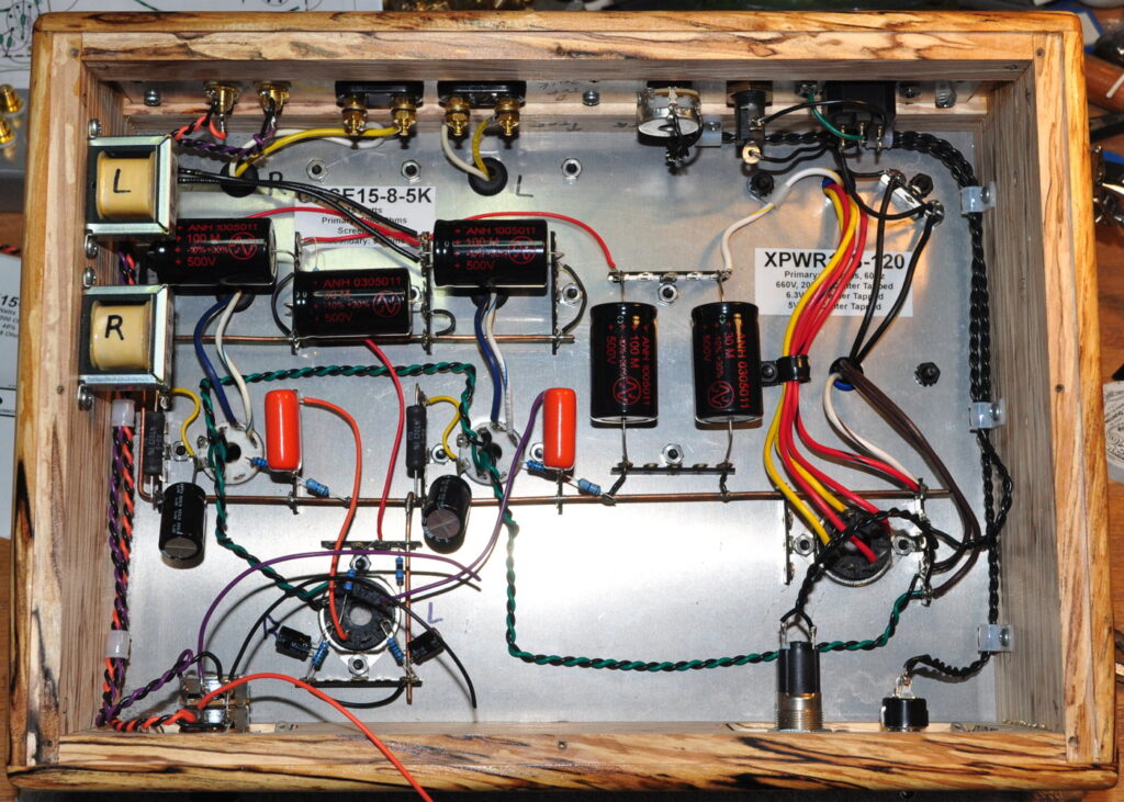
I got a chance to do a little work on the amp today. I managed to install the top plate on the spalted alder chassis, install the filter inductors for the power stages, connect the output transformer secondaries to the speaker terminals, and wire in the power transformer primary and indicator light.
This doesn’t look nearly as cramped as I thought it would.
I haven’t wired in the volume controls to the driver stage yet. And, obviously, the primary filter choke is not yet installed on the left side. But I did get enough wired to check out the power transformer installation. The 120VAC primary, the high voltage circuit, and filament circuits all look good. I also still need to install the safety ground wiring to the exposed plates. Only three plus the top plate in this amplifier.
The high voltage winding, without any load, measures ≈700v; about 40 volts above specification. So with the rectifier plugged in, but with no other tubes in the amp, The B+ on the filter caps is about 495v. This is why I specified 500v filter capacitors for this amp. Under load the B+ voltage will obviously come down quite a bit, and only the first capacitor will see the highest value because of the dropping resistor. But I wanted to make sure that if I (or someone else) ever pulled the power tubes and turned on the amp, then the B+ would not be so high as to destroy filter capacitors. And just in case anyone is wondering, the coupling caps are 716 series rated at 630 VDC. There I have some real margin. For reference, the target B+ voltage on the power stages is 400 VDC.
Of course, I have no intention of ever powering up this amp without power tubes installed. However, it is just good design practice to make sure all these off-nominal conditions are properly handled in the design.
As always, questions and comments are welcome.

