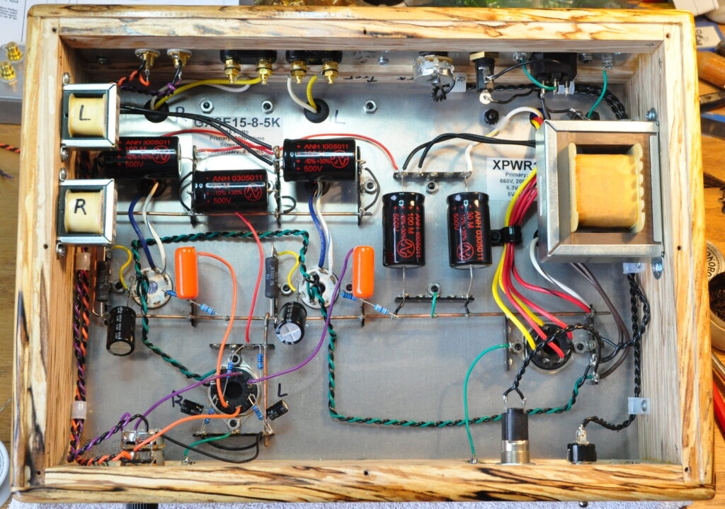
This morning I took a little time to complete the major wiring of the amplifier. Everything is in place except the B+ dropping resistor.
This includes the input wiring from the volume control, all the safety ground wiring, the main filter choke, and the signal ground to safety ground tie. Here is how it looks this afternoon.
The dropping resistor ties into the terminal strip at the top of the two vertically oriented filter capacitors. It will bridge the white/yellow transformer lead and the righthand filter choke lead. At first I’ll power up the amp with a variable resistor in this position and adjust for a B+ voltage of 400VDC at the power stages. Then I’ll measure the resistance and select a fixed dropping resistor that’s as close as possible.
Before I can do this however, I need to construct a cradle to hold the amp upside down so I can install all the tubes. This will probably have to wait for tomorrow.
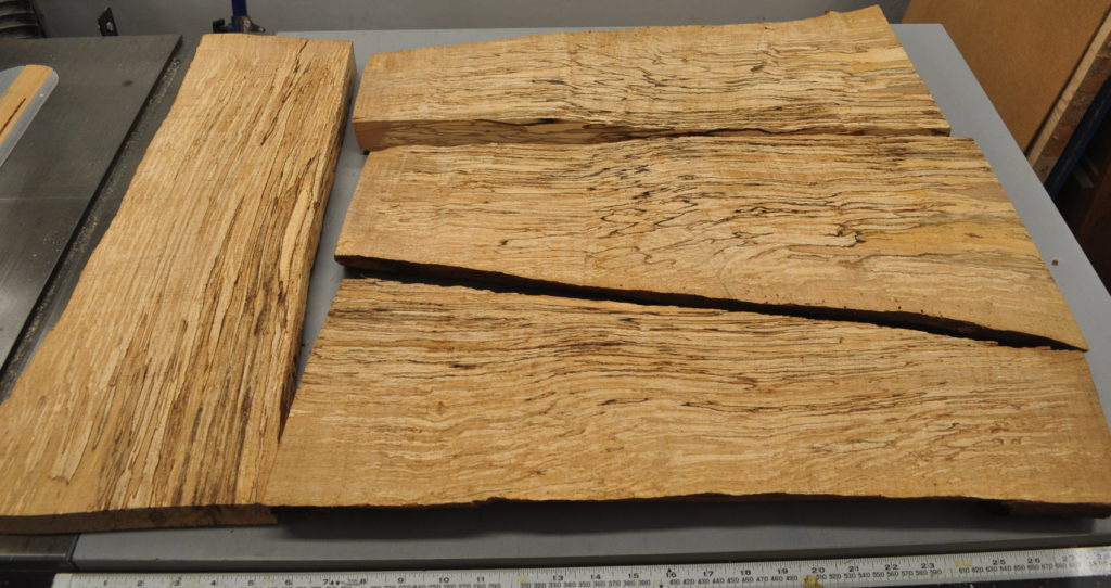
While I was reviewing my photos of this project, I received a little reminder of how far this amplifier has come. Here is from where I started with this project.

These are the original slabs of spalted alder which my friend brought over to show me at the beginning of May. It was these slabs that served as my inspiration for this amplifier.
I am really looking forward to getting this project tested and completed. It won’t be long now (I hope).
As always, questions and comments are welcome.


I love to look back and see how far a project has come along.
I regret I wasn’t in the habit of taking photos along the journey for so many of the past adventures.
This looks good!