I had the opportunity today to sit down and finish up the wiring on the source selector unit chassis. It has been a productive week for this project. Now that the chassis is in good shape, I’m free to move on to the assembly and wiring of the vacuum tube circuits.
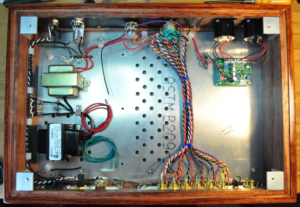
Here is how the internals of the chassis look this afternoon.
The most notable change from yesterday is that all the twisted pairs between the selector switch and the input jacks are soldered in place and neatly bundled. Also visible in this picture is the wired gain control, the completed power wiring, and the complete indicator lamp wiring.
There is a little wiring that will come after the vacuum tube circuits are complete and installed. This wiring includes the output signal wiring, the signal ground side wiring of the ground lift switch, the input wiring to the VU meter driver board, and the completion of the chassis ground wiring.
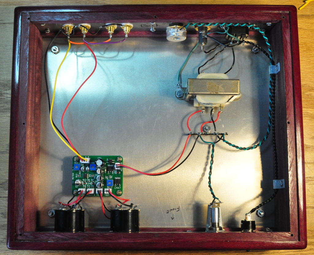
Overall I think the chassis is in good shape. I was a little apprehensive going into this project about the complexity of the chassis wiring. However, I think the careful layout planning really paid off. It’s interesting to compare this chassis with the internals to the “Purpleheart” Signal Meters project. Here is the internal view of that chassis.
It was this simpler project which was my inspiration for the bigger, more complex preamp project. It also served as a good prototyping effort on using these prepackage signal meters. I think this new project is going to be even nicer than the “Purpleheart” Signal Meters project. Now I need to switch gears and get back to working on the vacuum tube portion of this project.
As always, questions and comments are welcome.


Appreciate the frequent update of the progress in the project. Can’t wait to see what it looks like with tubes.
Me too. 😉