Have you ever made a mistake? Not a typical everyday little mistake like forgetting to run an errand, but a blunder of such proportions that you’re shocked by your foolishness? One that leaves you thinking you couldn’t have been that naive, that foolish? Well I did. And it left me with significant embarrassment, as well as some smoke coming out of an amplifier.
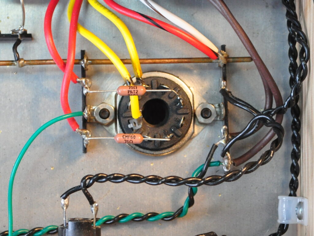
It happened when I made my recent update to the 6L6 Spalted Alder amplifier. Back in October I discussed the failure of the amplifier and the changes I made to the transformer/rectifier wiring in the post A Slight Revision to the 6L6 “Spalted Alder” Amp. In that post I detailed how I calculated the additional plate resistance to ensure the proper operation of the 5AR4/GZ34. And I said that I had some 75Ω/1W resistors handy. These are the resistors I installed. They looked like this when I installed them.
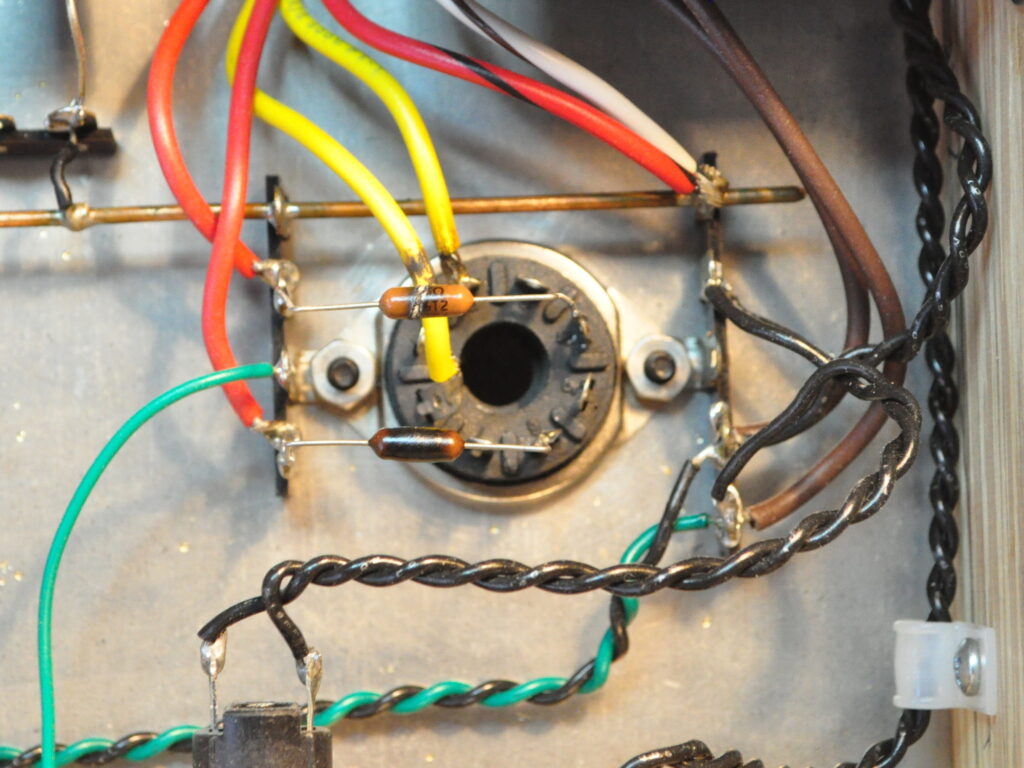
And this is where I made my blunder. I looked at the total amplifier power supply current load, divided by two, and assumed this was the average current in each leg of the rectifier. Which, strictly speaking, is true. For the average. The total design current is about 140mA. Using half of this value (i.e. 70mA) and the 75Ω resistance, gives a power dissipation for the resistors of about 0.37W. This means that I assumed that the one watt rated resistors would be more than sufficient. But this is wrong. Not just a little wrong, but catastrophically wrong. After maybe thirty hours on the amplifier, the resistors looked like this.
The upper resistor has failed and measures in at ≈195kΩ. The lower resistor is still measuring at ≈75Ω but is clearly on it’s way to total failure. So the question remains as to how these high grade, 1W rated resistors got into this condition while dissipating less than 4/10th of a watt.
My failure was obviously in the assumption I made in determining the resistor currents. I assumed average current. However the power dissipated in a resistor is not based on the average current. It is based on the integral of the instantaneous current waveform squared, integrated across one full cycle of the waveform. In short, i^2 * R, not I*R. Oops!
The embarrassing part in this is that this is a typical first year Engineering student kind of mistake. For a career electrical Engineer to fall into the trap is inexcusable. And the worst part is that it took me about half an hour of pondering those two burned up resistors, before I finally realized my error. Needless to say, I was a little sheepish.
So to fix the issue I went back to the initial power supply design. In a center tapped rectifier, capacitor input supply like this one, the current does not flow in each plate (or diode) for an entire half cycle. Because of the voltage developed across the reservoir capacitor, the current can only flow when the transformer secondary voltage exceeds the capacitor voltage and the rectifier drop. The result is a pulsed current waveform with a duty cycle far below 50% (or 180°). Since the pulsed current must supply sufficient charge to the reservoir capacitor in this short time, in order to supply the total supply current (Q/t) over the full 180° cycle, the magnitude of the waveform is significantly greater than the average.
Going back to my initial calculations, I had found that the peak repetitive plate current value was approximately 5.6 times the average plate current value or ≈400mA. I also calculated a duty cycle of about 18%. Using these values and just assuming a square waveform (i.e. worst case), the instantaneous power dissipation is ≈12W during conduction. With a duty factor of 18%, the average power dissipation is 2.2W. So I was over loading the original resistors by ≈120%. I’m actually really surprised that they lasted as long as they did.
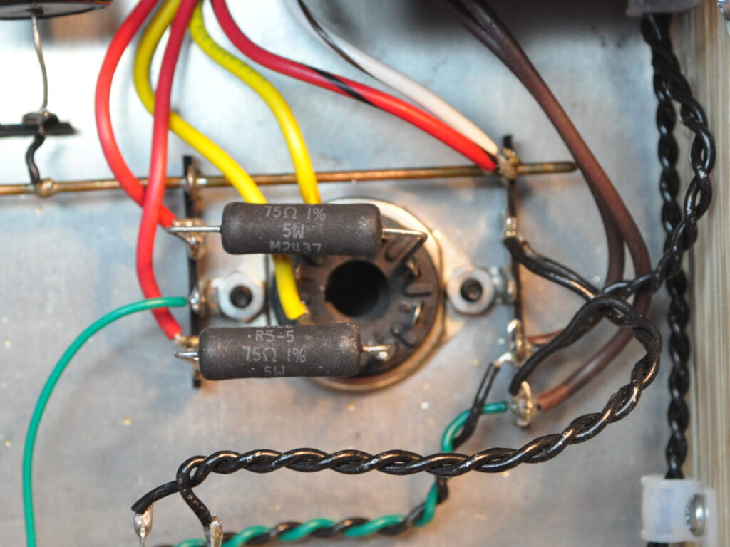
To fix the situation I ordered some new 75Ω resistors with a hefty 5W power rating. The parts I used are Vishay Dale RS00575R00FS73. These are a 75Ω/5W, 1% tolerance, wire wound resistor, with a high temperature (>350°C) coating. These resistors should not have a problem in the amplifier.
After removing the old failed 1W resistors, I installed the new ones. Here they are in place under the rectifier tube socket.
Once installed, the amp is working well once again. I also updated the schematics on the 6L6 Spalted Alder project page to reflect the power rating of the new resistors. I hope no one has followed my lead and installed 1W resistors. If so, I apologize profusely.
As always, questions and comments are welcome.
Update (18 Dec 2024)
Well, the amp has been running for about a week for between four and eight hours a day. It is working flawlessly and sounds great. Looks like it’s finally fixed.


Those 5W resistors look well-suited to the job. Thanks for sharing the story!
Pingback: A Slight Revision to the 6L6 “Spalted Alder” Amp | Cascade Tubes