
I haven’t talked about the new amp in a while so I thought I’d share current progress.
The “new amplifier” to which I am referring is the upgrade to the 6V6 Marblewood design. I went over my objectives for this amp in my posts “You Can’t Always Get What You Want” and “Shifting Priorities”. I have made some progress in the last six weeks or so.
First, the design and layout are finally complete. So all the design work is done. This includes the circuit design, chassis design, internal layouts, and finishes. Now I’m progressing to the build stage.
I decided to use the maple burl chassis I had rough cut for another project. I talked about that in the post “When it Rains, It Pours!”. As a reminder, the cut chassis boards look like this.
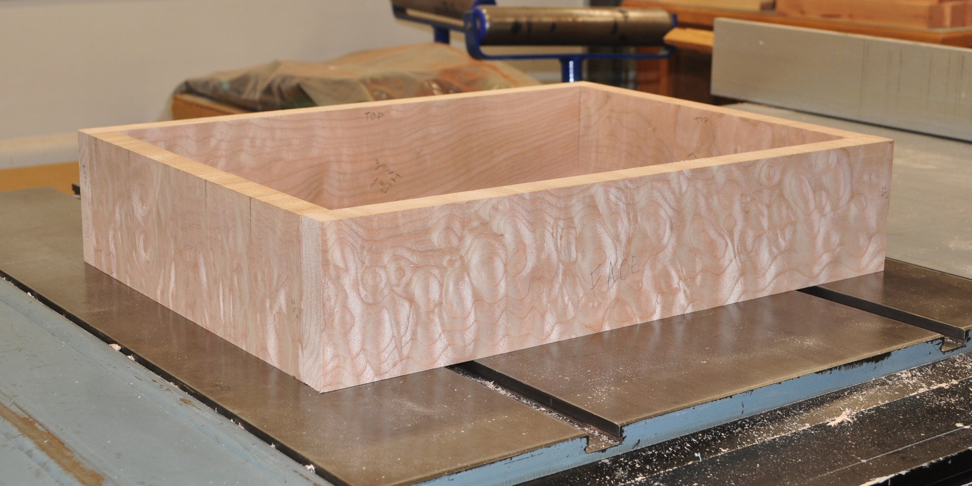
Since this picture was taken I’ve trimmed the boards to the proper lengths for this project, cut all the corner joints, and cut the recesses for the top and bottom plates. I haven’t made the chassis openings yet but will do so as soon as I get some warmer weather. This is a striking piece of wood. It’s the same wood I used for my little Volume Control project all those years ago. It should finish to a similar tone as the maple in that project.
In those earlier posts, I mentioned that the power transformer for the new amplifier is an Edcor XPWR009. What I didn’t mention is that the transformer is not new. In fact it’s from my prototyping station.
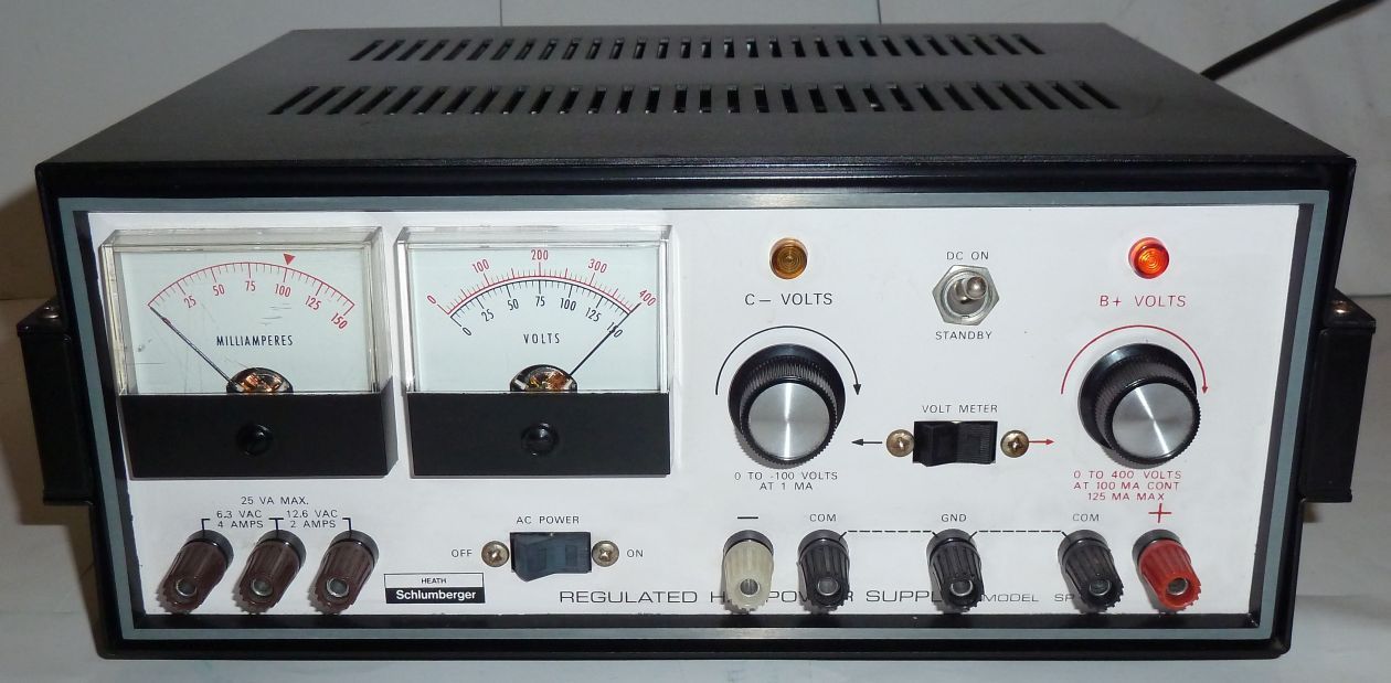
I still use the prototyping station all the time. However, some years back I acquired a Heathkit IP-17 high voltage power supply. Since then I haven’t used the integrated power supply on the prototyping station. The IP-17 is a much better option.
Since I had to remove the transformer from the prototyping station, many of the leads had been trimmed to appropriate lengths for that design. So I took some time today to splice some longer leads on the transformer. After I did that, I decided I would do a quick prototype of the supply with a 5U4 rectifier to see what voltages would look like at load. I constructed the prototype using several prebuilt jigs and some test equipment. Here’s the prototype on my work table.
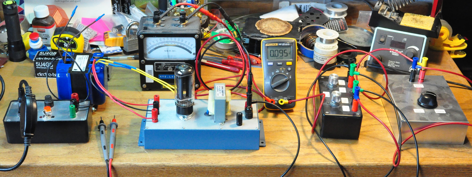
This is just a basic power supply but at 95mA (the approximate total load of the new amplifier) the voltage after the first LC filter was ≈325v. Since I’m looking for a B+ in the neighborhood of 300v this is a good result. I’ll lose probably another 5v or so in the channel specific filters. Since 320v is only ≈6.7% above target, I may not even bother to include a dropping resistor. I’ll have to wait and see. The current layouts include a PS dropping resistor.
So that’s the progress made to date. As soon as the chassis wood is complete I’ll cut the metal and begin fitting everything together. Then comes assembly. This is the stage where I begin to get excited about new projects. With warmer weather coming soon, the pace should pickup on the project considerably in the next couple of months.
As always, questions and comments are welcome.
The wood frame of the chassis looks amazing – Excited to see the next step!
I agree it looks quite striking. Almost has a 3-d effect without any coating.