
Lately I’ve been looking at a revised amplifier design based on the Marblewood project. The intent of the redesign effort is threefold. First, a different and more widely available rectifier tube. Second, an improved, if slightly more complicated, power supply design. And third, some potential improvement in the low frequency response. As it turns out, you can’t always get what you want. But also, two out of three ain’t bad.
The first objective is relatively simple. The original amp utilized the Edcor XPWR106 power transformer with only two secondaries; a center tapped high voltage winding for B+ formation and a single 6.3v filament winding. I decided that I wanted to go with a standard (and widely available) 5v filament rectifier, the 5U4. So the new design will use the Edcor XPWR009 instead. This transformer has the same high voltage secondary, albeit at a somewhat higher current (175mA verses 125mA), the same 6.3v secondary, and includes a 5v/3A secondary for the standard 5v filament rectifiers. It also doesn’t hurt that I have one on hand which I am not using. This saves me ≈$122 USD on the transformer.
The second objective is a little more complex, but not much. In the new design I have preserved the overall power supply topology and changed a few component values. The first capacitor has been reduced to 33µf. The primary filter choke has been increased slightly using a Triad C-14X 6H/200mA choke in place of the 5H Hammond in the original. And the 200Ω resistors in the final power stage filters have been replaced with Hammond 154M 2H/100mA chokes. These changes support the 5U4 rectifier. The rectifier only requires about 20Ω per plate at these voltage levels and the XPWR009 provides about 36Ω per plate so no rectifier plate resistors are required. These changes also provide significantly better channel separation between power channels. Finally, the filters support lower overall ripple levels in the power stages for a (theoretically) quieter amp.
The third objective, improved low frequency performance, is much more complicated. I would like to remind everyone that the low frequency -3dB point of the Marblewood amplifier is ≈35Hz. Personally I don’t consider this a flaw. There is precious little sound energy below this level in most recorded music, most people’s hearing is about 100dB less sensitive to these frequencies than at midband, and the blind test perception of musical quality, when eliminating frequencies below 40Hz, is virtually 100%. This is why I didn’t worry about it in the first place during the Marblewood design process.
However, for this design, I was hoping to improve on this frequency response a little, perhaps by 5Hz, so long as it didn’t take major machinations. This desire is rooted in my interest in quelling the flow of comments I routinely get from people who have never listened to the amp as designed. So I thought If I could get the response down a little bit at the low end, I’d get less grief from the internet bloviators. But this proved more challenging than I first thought.
The low frequency response of the Marblewood design is controlled in four separate places. These are labeled in the figure below.
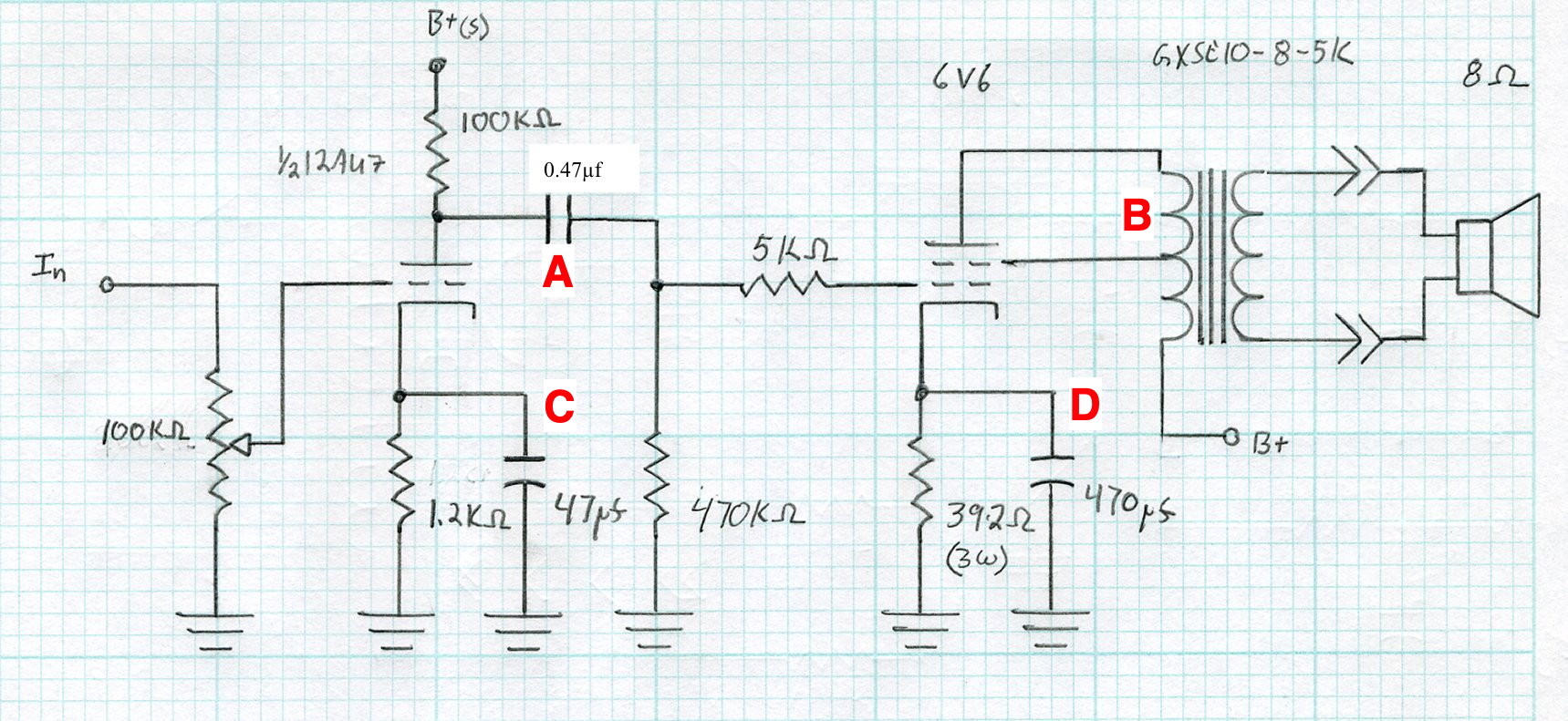
The points labeled “A” and “B” represent poles in the overall gain function of the amplifier. These have a -20dB/decade loss factor below the pole frequency. The points labeled “C and “D” are high pass filters in the feedback path of each cathode biased active stage. These poles are simply “half way” points between the bypassed and unbypassed gain functions of each active stage. Because of this, the difference that changing points “C” and “D” can make in the overall frequency response of the amplifier is limited to these gain differentials relative to their original positions. So I went back and revisited the marblewood design data.
The driver for the marblewood is simply the 4S universal preamp. This stage, with the 12AU7 and the 6V6 grid resistor, has a cathode impedance of ≈980Ω. With the 47µf capacitor this puts the high pass frequency at ≈3.4Hz. The stage loss at 20Hz due to cathode bypass is only about 0.2dB. Clearly increasing the driver stage bypass capacitor is not going to help in any meaningful way.
The power stage characteristics in UL mode are difficult to calculate. Specifically, the effective plate resistance is problematic. We do know that although much better than in pentode operation, it is significantly higher than in triode operation. Since cathode impedance is based on the parallel combination of the cathode resistor, and the plate and load resistances divided by the effective voltage gain, it is safe to assume that the latter is going to be significantly higher than the former. So if we estimate that the cathode impedance is 90% of the cathode resistor (a reasonable if not precise assumption), this is ≈350Ω. With the 470µf bypass capacitor, this puts the high pass frequency at ≈1Hz. This means that there is insignificant loss at 20Hz so increasing this capacitor will also have virtually no effect.
This leaves the two main poles at “A” and “B”. The first of these, “A”, has a point impedance of ≈480kΩ putting the -3dB frequency at ≈0.7Hz. This means that the loss at 20Hz due to this capacitor is only about 0.15dB. Again, no meaningful improvement will be made here. So all that’s left if I want to improve the low frequency response is the pole at “B”, This pole is formed by the power stage output impedance and the primary inductance of the output transformer. I really shouldn’t be surprised by this. It just means that I paid attention the first time and made sure that the Marblewood’s low end frequency response was dominated by the output transformer characteristics.
The issue here is how to change the response. I talked about this issue in detail in my blog post “A Consequence of The Quest for 20Hz Roll Off” over 10 years ago. As a refresher, here is the relation relating the power stage low end frequency response to the midband response.
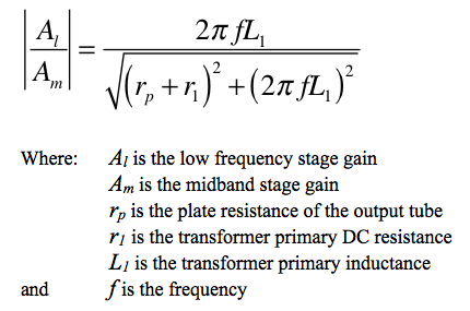
Since I want to preserve the operating point of the output tube, changing the plate resistance, rp, is not an option. This leaves the primary inductance of the output transformer. So to raise this inductance, I would need to switch to a larger transformer. Now the Marblewood amplifier uses the Edcor GXSE10-5kΩ transformer and has a response that is ≈-6dB from midband at 20Hz (or -3.7dB at 30Hz). It is interesting to look at the 6L6 Spalted Alder Amplifier for comparison as it uses the larger Edcor GXSE15-5KΩ output transformer.
The 6L6 Spalted Alder amplifier with its larger output transformer definitely has better low frequency performance. It is only down -2.3dB at 20Hz and ≈1dB at 30Hz. The implication is that I would likely get several dB of addition response at the low end by switching to the larger output transformer.
There is a catch however; and hence the title of this post. As of this writing, a pair of the GXSE15-5kΩ transformers would likely set me back by about $200 USD after shipping. This is a significant chunk of cash. Especially since I already have a set of GXSE10-5kΩ output transformers which are not committed to any project. The question is then, are those few dB of low end performance worth the cash it would set me back to get them? Personally, I think not.
So I will go ahead with the revised project because the difference would probably never be apparent in any real world listening conditions. Time to think about a chassis.
As always, questions and comments are welcome.
Pingback: An Update on the Update | Cascade Tubes
Pingback: Shifting Priorities | Cascade Tubes
I took your Marblewood and went a different direction – all Noval sockets; 6CA4, EL84 and 12AU7; GXSE10-3.5K OTs; powered by Hammond 270DAZ. As the PT is only rated for 104mA at 550v, the outputs are wired in Triode mode, 280vak, 10vk, 37mA each. The amp doesn’t have a lot of bass, but it is so fast. Pairs well with KRK studio monitors. I set it up with an active crossover and a Class D module running a pair of woofers, very nice.
Hi Matt, enjoyed reading this post and gaining some insight on your design considerations.
A question regarding the low frequency response. You state that the -3 dB point on the Marblewood is about 35 Hz. On your 6CY7 V1, I believe your -3 dB point is about the same (35 Hz). In your 6CY7 V2 build (which addressed the low-end shortcomings), you state “When I A/B tested the amps, the improvement in the low end was very apparent.”
Would that not apply to this as well? Wouldn’t it make sense to use the 15W output transformers for a major revision to address UL low-end?
Apologies for the bloviation.
Absolutely! If I were buying new output transformers for this project I would likely spring for the GXSE15 in place of the GXSE10. However, seeing as how I already have not only the power transformer, but a set of GXSE10-5K transformers sitting on the shelf, that’s what I’ve decided to use.
The ≈$200 USD that a set of GXSE15s would set me back seems like a high price to pay for a few Hertz of response at the low end. I know that when I side by side tested the 6CY7 amps I could tell the difference, but I listen to the Marblewood several times a week and I have never felt like the lower register was lacking. As I said, if I didn’t already have the GXSE10s, I would spring for the larger outputs. But in my current circumstances, I just can’t justify the additional expense.
Makes sense. Do you feel that for most of your amplifier designs, it is safe/acceptable to substitute output transformers with higher power ratings? Or are there potential downsides to this in terms of performance?
Yes; within reason. More so for the UL designs due to their higher power stage output impedance, less so for the SETs.
For the most part, selecting an output transformer with a higher primary inductance is going to improve the low frequency response somewhat. But remember that this comes at a cost of responsiveness at all frequencies. So it is possible, with too high a primary inductance, to take an amp that is very fast and transparent and bog it down so that anything fast becomes muddy and dull. Of course, there are ways to address this, but not without completely altering the harmonic structure, and hence the sound, of the amplifier.
Like everything, there are tradeoffs to be considered.
Matt,
Based on what I have learned from audio pros – the vast majority of recordings have a steep roll off at 50 Hz. This is a holdover from the old vinyl days. Most speakers struggle to reach 50 Hz. As you stated, the reproduction of low frequencies requires massive amounts of power – beyond anything home audio can produce. There is almost no music below 40 Hz..
My motto is – If you can’t hear it, don’t amplify it. The old 50 to 15k hi-fi frequency range is truly valid.
Ciao Matt. Saluti da Palermo.
Quindi posso attendere alcune modifiche per migliorare l’ottimo Marblewood?
Se era possibile anche un po’ di potenza in più.
Angelo Guzzo
> Hi Matt. Greetings from Palermo.
> So I can wait for some modifications
> to improve the excellent Marblewood?
> If possible also a little more power.
If you have already built a Marblewood, I would recommend not changing anything. The new amp requires a different power transformer and different rectifier. These are big changes which are really beyond “modification”.
As for the power output, I will make the same recommendation I always make. Look for different speakers with about 3dB higher efficiency. This is the equivalent of doubling the output power of the amplifier. 🙂
Matt,
I know you used XSE OTs in the first 6CY7 amp and then changed in the second version. Do you think the XSE transformers are a good option for a budget build where not having steel end bells doesn’t matter?
Dan
The XSE transformers have a narrower bandwidth than the GXSE. There is a plot on the 6CY7 V2.0 “Zebrawood” Amp page comparing the two amplifiers. The differences in the low end performance are mostly due to the differences between the XSE and GXSE transformers. Even for a “budget build”, I would recommend the GXSE transformers if you can afford them at all.
That graph is very informative – Thanks