A big part of building custom vacuum tube amplifiers is layout. Even when the schematics are finalized and parts are ordered (and even delivered) the preparatory work is not over. With this phase comes the arranging and rearranging of transformers, tube sockets, potentiometers, switches, jacks, terminal strips, and all the other miscellaneous parts that make up the final amplifier. And this is where some simple quality tools can make all the difference.
The first tool I find indispensable for performing the final layout and marking up metal prior to cutting is a good quality ruler. Here is the one I use.
It is stainless steel, 12″ long and 1″ wide, with gradation ranges of 1/8″ and 1/16″ on one side and 1/32″ and 1/64″ on the other. This is a nice ruler with fine but deeply etched markings. This particular one also has a “hook” end which is valuable when working with metal sheet. Most of the rearranging for me takes place on the computer, but when it comes to checking part dimensions and putting the actual cutting and tooling marks on metal plates, this ruler is indispensable. By the way, this ruler did NOT come with the nice leather sheath shown above. This was made for me by a good friend who does leather work as a hobby when the cheap plastic sleeve it came with finally came apart.
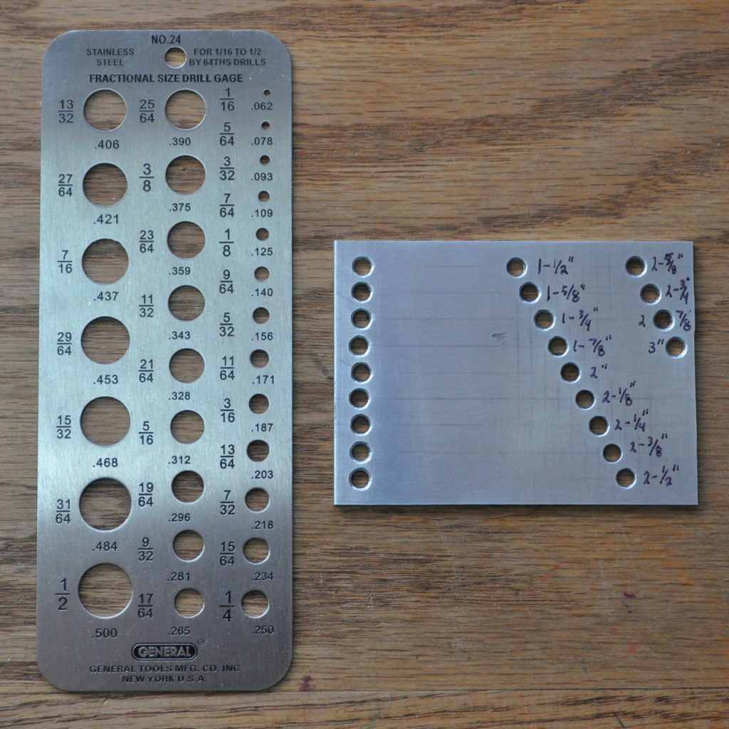
A couple of more tools which help out are some simple gauges. Here they are.
 The one on the left is a simple drill gauge. Its principle value in layout is to check the actual sizes of switches, potentiometers, indicators, and the like. It is also good for checking the appropriate size of screw clearance holes. I have these in my workshop for quickly double checking drill sizes and found them so useful in gauging electrical components that I finally bought a dedicated one to live on the desk in my office. It also makes a handy straight edge. This one is also stainless steel with deeply etched markings.
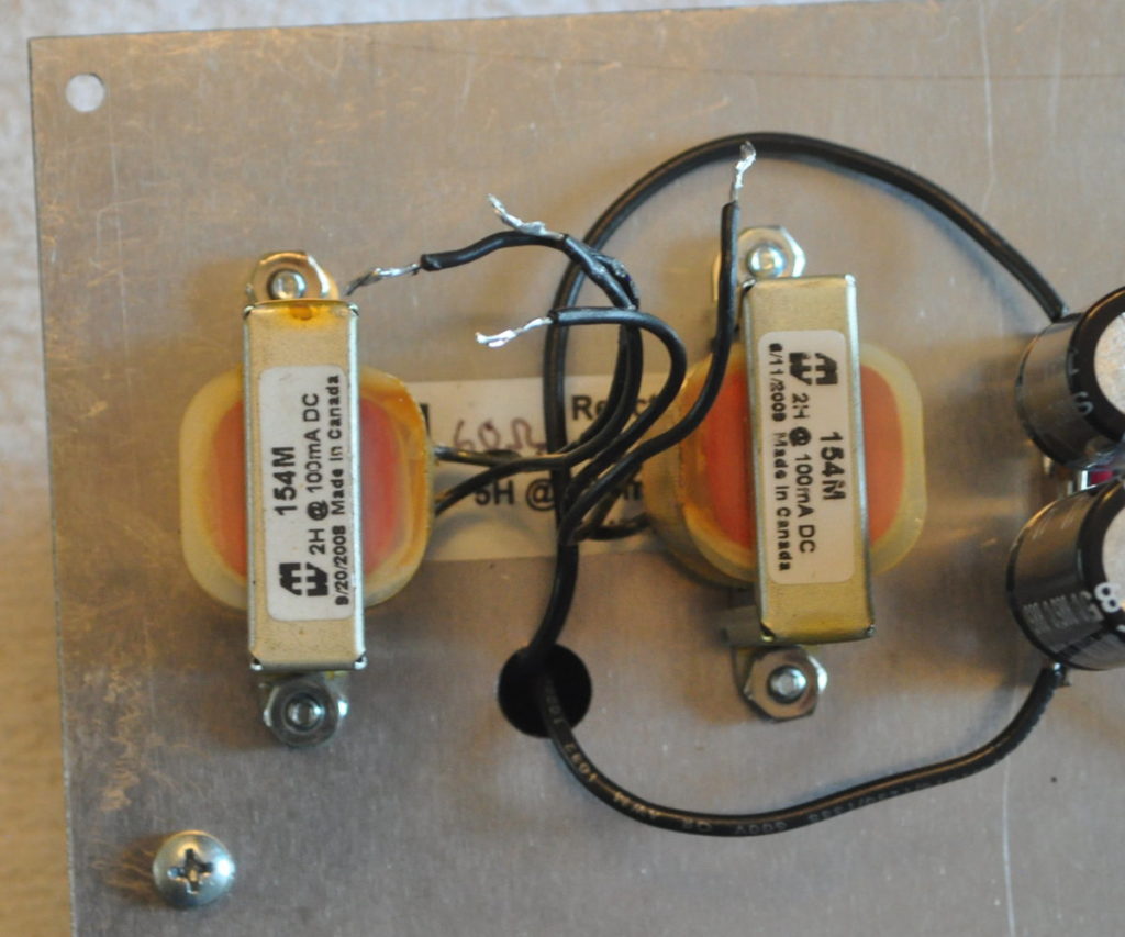
The gauge on the right requires a little explanation. Anyone that follows my amp builds knows that I like to take advantage of transformer and tube socket mounting screws for mounting other components underneath the top plates of my amps. Here is a good example from the 6CY7 amp where I mounted a couple of Hammond 154M 2H chokes on the mounting screws for a Hammond 193H enclosed choke mounted on the top of the amp.
I also sometimes mount terminal strips between these same screws as on the recent 6V6 Marblewood amp power transformer. The key to doing this is to realize that the mounting hole separation for most terminal strips and open frame inductors is fixed whereas the mounting feet on most end-bell transformers and chokes have slots that will accommodate a variable mounting screw distance from front to back. For example, the Edcor GXSE10-8-5K output transformer can use a back to front screw separation anywhere from about 1-5/8″ to about 2″. Which brings me to the homemade gauge in the photo above.
This gauge allows me to quickly check the mounting hole separation of small chokes and terminal strips, and then check those dimensions against end-bell type transformers and chokes I have on hand. Very often it is possible to find a hole separation that works for both. And if I am still uncertain, I can even temporarily mount both on either side of the gauge plate with some 6-32 screws to ensure the arrangement will work out.
So what type of gauges and tools to other people use when laying out their amps? I’m interested in finding out.


Oh my goodness! Incredible article dude! Thank you, However I am having difficulties with
your RSS. I don’t know why I am unable to subscribe to it.
Is there anyone else having similar RSS issues?
Anybody who knows the solution can you kindly respond?
Thanks!!
As I return to a fascination with tubes that should have found me building something 20 years ago, I realize I’m probably better prepared now versus then. One of the “tools” I have now is the use of a decent graphics program…just an old version of Adobe Illustrator. But it lets me do a physical layout in full scale, and move everything around as needed, before a single hole is drilled or punched. It’s not 100% infallible, because datasheets aren’t always perfect, but it’s an excellent place to start.
Hi Matt,
I think your two gauges are a great idea especially the gap gauge for spacing. I don’t think I put enough thought into chassis layout so this is interesting for me. Any more hints?
A little off subject, I saw your lacewood sitting in a cradle in an old post. This has made me go away from testing an amp on its side. As you say, safety first. I built an adjustable cradle. See it at http://www.theleathershop.biz/test-jig.html
It is probably the most useful item I posses.
Love the amp cradle. I keep telling myself I should make one but I never get around to it. I think I’ll copy your design. Thanks for the idea.
Nice post. I need to order a screw gauge. I’ll copy your drill gauge with a 3D print, great tip, thanks.
I use a combination square to keep layout lines parallel and perpendicular. Plus it doubles as a ruler.
Also, a low cost machinist’s caliper to check clearance for shafts, connectors, etc. Had to reduce the diameter of some screw heads to mount speakers – turned one down to what was needed – measured it with the caliper – quickly mass produced 11 more using the calipers as a gauge.
I also put masking tape in the areas I will be marking, to help avoid marring the cabinet.
Most importantly, a clean workbench and good lighting (the old eyes ain’t what they used to be)
I most assuredly agree, especially with the good lighting. A good magnifying glass is also essential sometimes. I have several good magnifying glasses at my work table. Including the swing arm lamp with the florescent ring light and large magnifier in the center.