Same Skin, Different Muscles
The 6V6 Lacewood amp was designed and built in the first half of 2011. At that time there were two important aspects to this build. The first was that it was partially an experiment to see if an alternating current filter supply would cause 60Hz hum in the output if the B+ supply was very clean. The second important aspect was that the UL power stage design was based on a pentode mode bias point pulled directly off the 6V6 data sheet. The amp turned out very well at it was my main listening amplifier in my office for several years.
Then in early 2016 I became acutely aware of the lack of good design data with respect to operating beam power tubes in the ultra-linear configuration. To remedy this, I performed a 6V6 UL optimization study to obtain some better design data for this tube. This is turn led directly to the redesign of the original 6V6 Lacewood amplifier using what I had learned.
The Electrical Design
Since I’ve always liked the look of the Lacewood amp I was not going to do anything to perturb the outside. This meant a redesign using the same transformers, main filter choke, filter capacitors and tube complement; a “stealth” redesign. Both the power and driver stages were to get a new design.
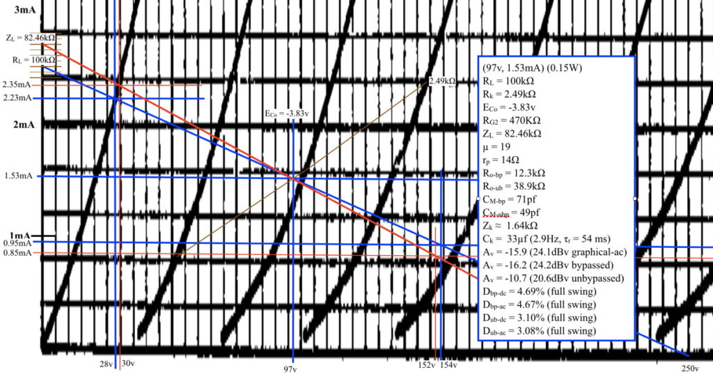
For the power stage, I took a bias point directly off the optimization table: Vp=275V, Vk=18.1v. Simple. For the driver stage, I no longer needed the soft (i.e. high 2nd harmonic) stage I had used before. Instead I opted for nice clean bias point with a much higher load. Here is the load line design.
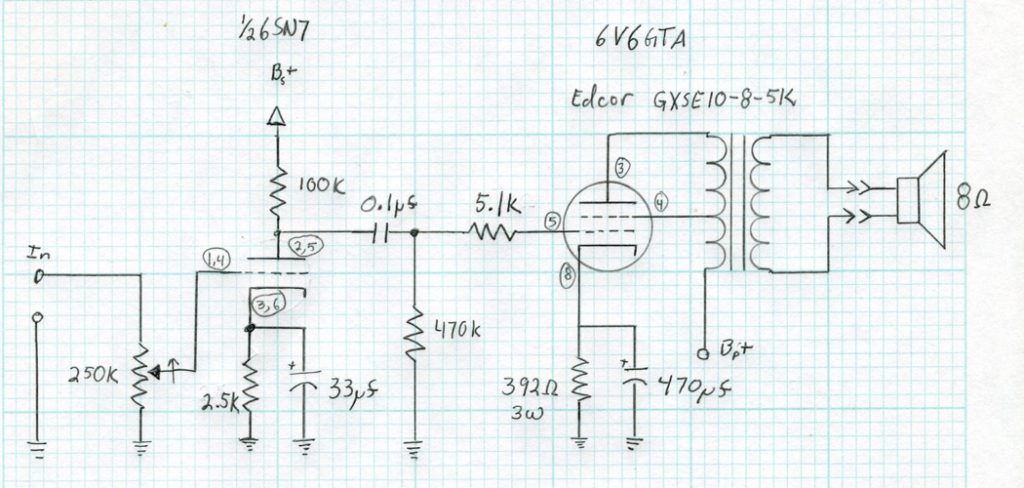
Along with a few calculations for frequency response, these bias points led to the following schematic for the amplifier proper.
This design makes use of what I learned from the 6V6 optimization study and uses a more appropriate bias and load for the driver section.
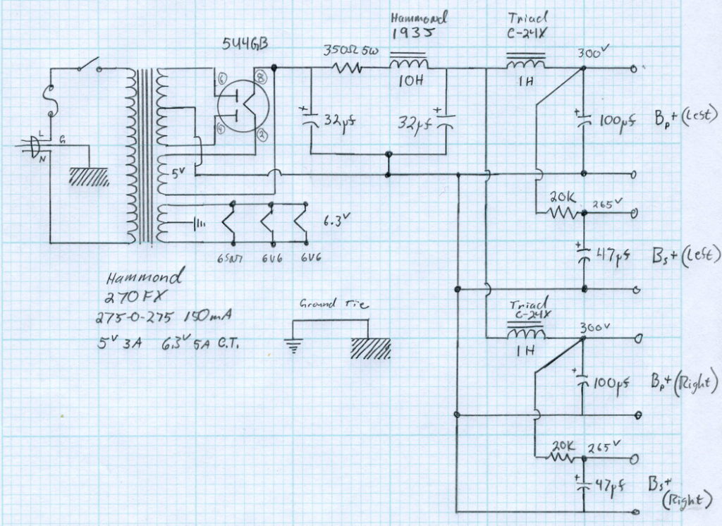
The power supply also takes a slightly different approach from the original. Instead of just driving the B+ ripple to preposterously low levels, I opted for low ripple and very good (dare I say “great”) channel separation. Here is the power supply design I used.
This power supply uses the same transformer and main filter choke, but in place of the single 5H choke in the original, it uses separate chokes for each channel. This puts about 70dB of power supply channel separation between the power tubes at the primary ripple frequency. As frequency goes up, so does channel separation. There is also an additional 57dB of power supply filtering between the driver and power tubes of each channel. This design virtually eliminates any channel crosstalk due to power supply coupling.
The Build
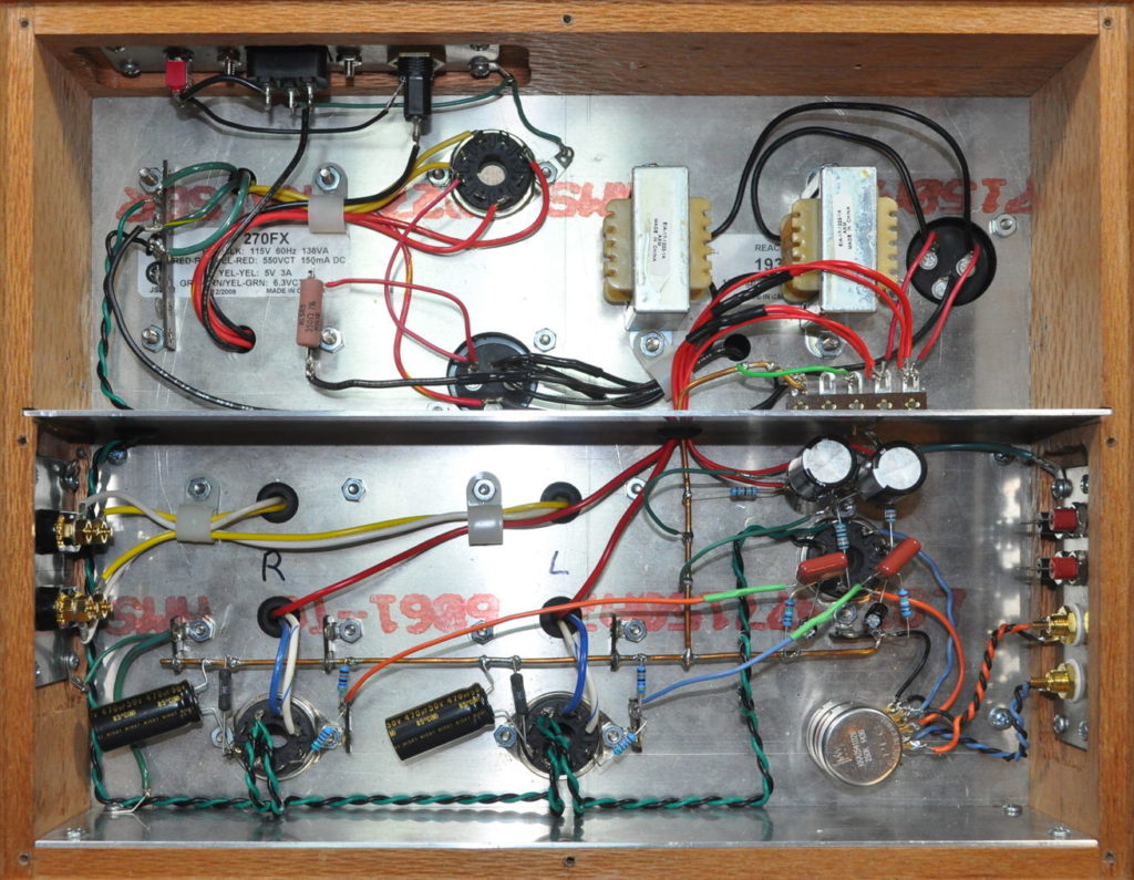
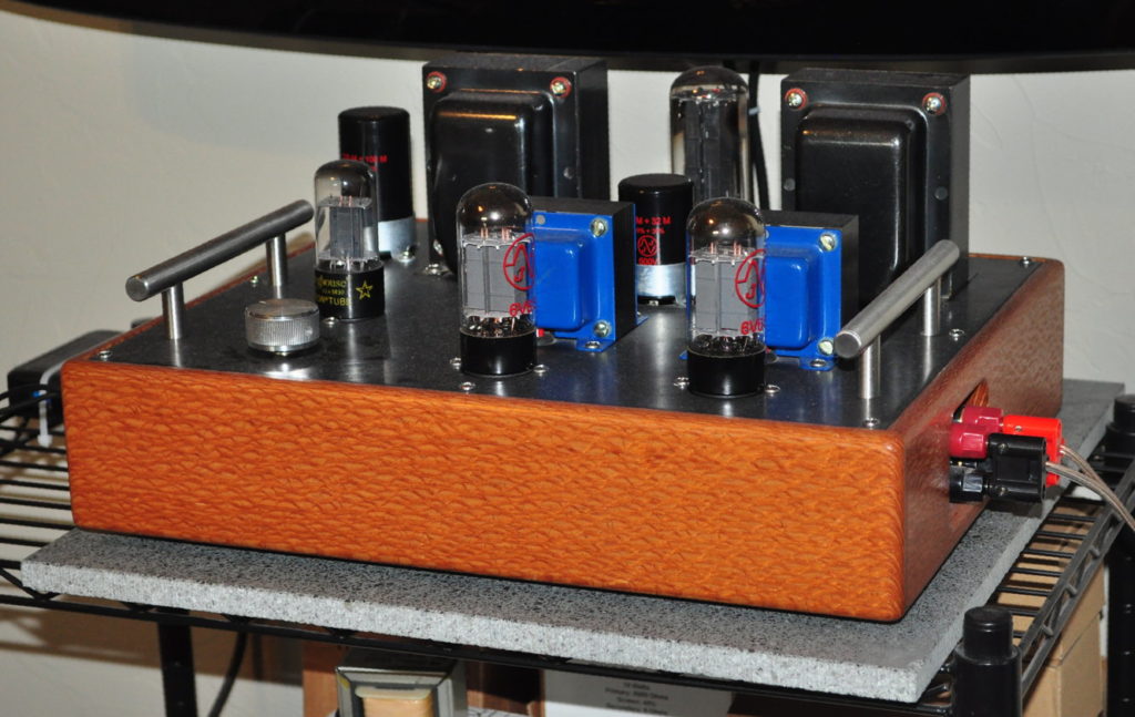
As I said before, nothing changes on the outside, only the insides get a new look. Here is an overall picture of the rewire.
This really doesn’t look much different from the original. The 5H choke is gone; replaced by the two Triad 1H chokes. The old $2 alpha volume pot has been replaced with a nice PEC dual control. The test point wiring has been removed (although the test sockets remain). And finally, much of the wiring is different.
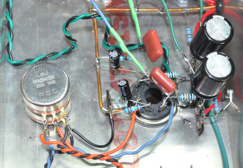
Here is a close up of the driver section.
This is actually much cleaner than the original. Some of the twisted pair wiring has been replaced by single leads. This change had no effect on coupling, hum, or noise; all are inaudible.
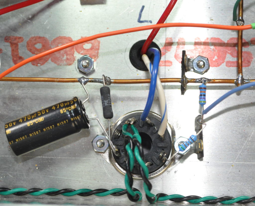
Here is the new power section wiring.
This is almost identical to the original. The only differences are the component values, and the addition of a small 5.1kΩ grid stopper resistor to control any bias excursions.
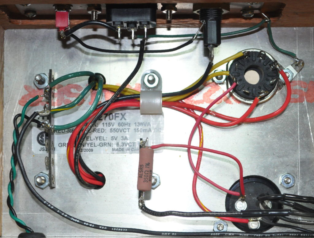
Finally, here is the primary power supply wiring.
This is virtually identical to the original. The only real difference being the addition of a 350Ω dropper resistor between the first filter capacitor and the main filter choke. Other power supply filter wiring is per the schematic above.
The Test
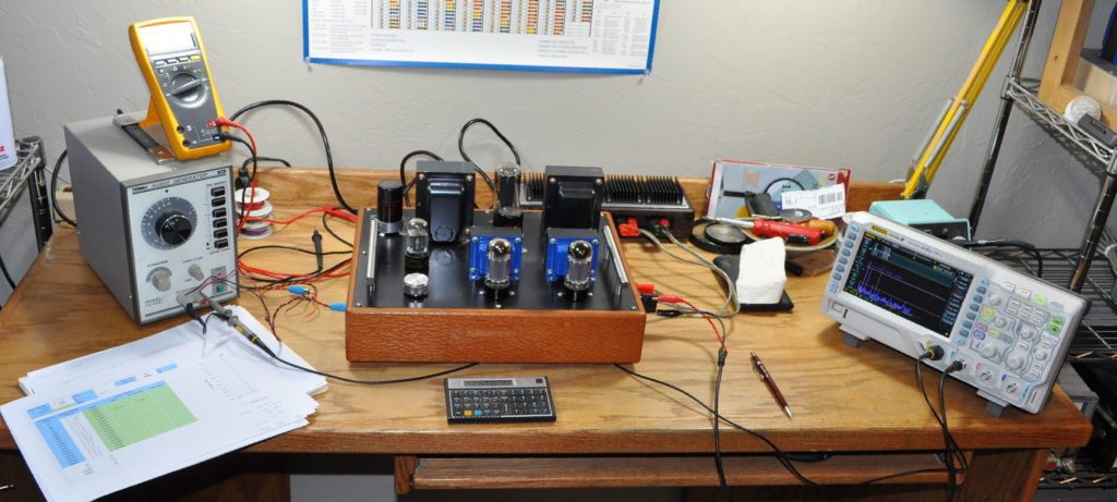
This amp got more testing than the original. There are two reasons for this. First I have begun to perform more testing on my amplifiers just so that I can hope to reproduce certain sounds I like in future builds. The second is that, as the first of my builds using the data from my study, I wanted to verify the optimization results in a complete amplifier build.
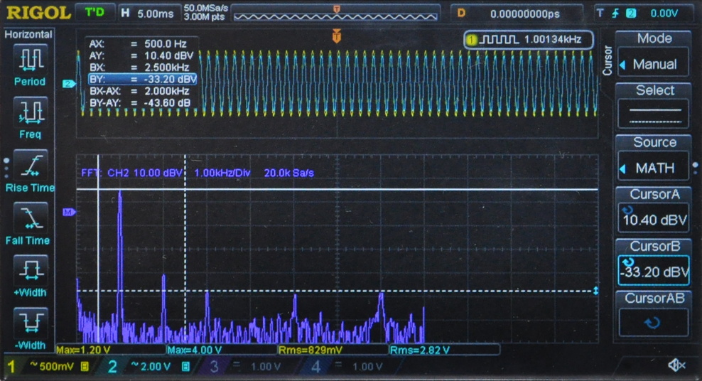
All the values for the amp look good. Voltages are about where I expect then to be and the output power, while about a dB low, is still a very acceptable level. The distortion at 1W is about 1.7%, mostly second harmonic. This is a good result. Here is what the distortion response looks like.
Ignore the 5th and 7th harmonics. These are a product of my signal generator.
Impressions
The amp sounds wonderful. It is perhaps a littler cooler (i.e. lower 2nd harmonic) than the original but the sound stage is incredible. This amp is very fast and very detailed. I am very pleased with the result.
This is once again the primary amplifier in my work bench area. It is now getting regular use as I design, prototype, assemble, and test new designs. Like a Phoenix from the Ashes, the Lacewood has been born anew.

Sorry Matt for bothering you with this question, my 6v6 Lacewood amp was working perfectly. Suddenly, I realized that the volume on both channels had dropped. I measured the voltages and they were fine (according to a chart you posted and another one I made when I made the amp). My test with the oscilloscope was to apply 1vpp 1kHz to the input, and at the output I got 3.1vpp, whereas in my first tests it gave me 7.44vpp. Can you give me any clues as to where to check? could it be the 6sn7 valve? Thank you very much!!
If it’s both channels, the first thing I’d do is verify the inputs (sounds like you did) then I would swap out the driver tube (i.e. the 6SN7). There are some failure modes which can affect both triodes simultaneously. After that, if the new driver tubs did not correct problems, I would check the voltages paying specific attention to the B+ voltages and the cathode voltages on both the driver stages and the power tubes. If all those look ok, then I would begin looking at the signal grounding scheme, Specifically the inputs and the volume control. Sometimes a bad ground in one of these two areas can manifest in the symptoms you describe.
If none of this works, shoot me an email and we’ll discuss where to go from there.
matt, did you measure the output impedance of the amp? with load and no load?
im curious about it
Thanx a lot
No. The output impedance of the amplifier is really set by the output impedance of the power stage at the quiescent operating point and the winding ratio of the output transformer. Since I had already chosen the operating point of the power stage based on the 6V6 optimization study, there is nothing I could do about changing the output impedance, even if I did know it.
I match the amplifier with high efficiency speakers with relatively stiff (i.e. high Qms and Qes) cones/drivers. I haven’t had any need to worry about output impedance or apparent damping factor.
Could the 6v6 be connected in triode mode? or do you need more b+?
Thanx Matt
Yes you can. But the cathode bias resistors on the power stages should be increased to approximately 510Ω (1W). Peak power output will be about 1.3W per channel with a warmer tone. No other changes are required.
How do you get to that number? 1vrms input?
I assume by “that number” you mean the 1.3W peak output power. That number is taken off a 6V6 triode load line. The design point in question uses a 5kΩ load and a 510Ω cathode bias resistor. Power stage bias point is about 300v Vp and 39.5mA Ip. This yields about a 20v cathode self bias. This assumes about a 325v B+ voltage.
At this operating point it’s about 1.5W delivered to the output transformer. Assuming about an 85% output transformer efficiency gives about 1.3W of peak output power.
Thanx Matt, im learning a lot with your designs and blogs
Hello Matt
! I’m trying to get the parts to assemble the lacewood, and when I want to purchase the opt, I have a question.
The edcor are guitar opt, according to their manufacturer. Does anything change if I put something similar to the Hammond 1628SE? Or wouldn’t the difference be noticeable in your design?
thanks for solving my doubts
If you build it with the specified output transformers, you get very nice performance. There is a gentle rolloff at the low end but it is not noticeable in any music to which I’ve listened. The Lacewood V2 is a very popular design and I’ve received no complaints about low frequency performance.
You could boost the low end with a bigger transformer (like the Hammond 1628SEA or the Edcor CXSE25-5K) but it would hamper the transient response somewhat. If you were testing two amplifiers side by side you might notice a difference, but it would be slight. Personally I don’t think the very slight change in performance is worth the much higher cost of the output transformers.
thanx a lot Matt!!
Hi Matt
I built your design, and I was listening and testing, it sounds very good and I like that it has a little more bass than my previous project (6v6pp in triode mode).
My voltages in general are a little lower, but they are close to your design.
Without any noise on any channel.
The only thing I see is that the tests with square waves at 20hz, 1khz and 20khz are a little strange, not to say deformed, perhaps it is because of my source, I have transformers and chokes made by hand by a local winder, thanks for any advice.
By the way, I’m testing it with some JBL A130 with 6ohm impedance and 87db sensitivity, I didn’t think 4watts would sound that much.
Personally I never test with square waves because once you have the pass band characteristic, the square wave response is redundant. If it sounds good to your ears, don’t worry about how square waves look. If it really bothers you, plot the pass band characteristic. That might show something unexpected, but I doubt it.
Enjoy your amplifier.
It is true what the square wave gives, it does not represent the characteristics of an amp, but since it is the traditional test, I did it, people like Jelabs present them.
Question, where would you place bledder resistors?
thanx matt!
A square wave is just a combination of a fundamental and its odd harmonics. If you don’t have a spectrum analyzer it can give clues to the bandpass characteristic of an amplifier. But with modern equipment and the ubiquity of frequency analysis tools, I see no reason to ever feed a square wave into an audio amplifier.
The placement of bleeder resistors is not critical. just about anywhere in the power supply is fine. I generally put then after the first LC (or RC if that the topology) filter stage. But they can be placed almost anywhere in the power distribution system. Just so long as there is a dc current path between the bleeder and all the filter capacitors.Which is generally the case.
Hi Matt, aways Fabrizio from Italy. One additional doubt… i used a 50k potentiometer. from halfway on there is some hum 120hz coming out. Shall i chase more carefully for ground loops or it might be the too low impedence potentiometer?
The 50kΩ value is smaller than I generally use but it shouldn’t be a problem. If you have volume control, position dependent, hum that is almost a grounding issue. My guess is that you have a ground loop somewhere in the input. It can also depend on the source driving the amp as its ground scheme will play a part.
Hallo Matt.
Greetings from Italy! I follow your blog and i learned a lot through your precise and detailed explanations. Thank you very much for this.
Now, after building the “universal preamp”, encouraged by it, i went on and decided to build the Lacewood amp. I had some sunused 6V6 around, no 6sn7, but a few 6J5 (half of a 6SN7) and 2C22 (the funny tubes with 2 caps, also equivalent to 1/2 of 6SN/). Had transformers recovered from other equipement, and an already made never finished adequate wood and metal case. My transformer was a 6,3 5A + 260V 400ma. B+ was a little low, and no central 0 tap to use rectifier, so i went SS, redsigned the filtering as CRCRCR to start with, to be later modified with some inductance. Finally the amp was ready, built “a la Japanese”, very rational and cared for. Worked flawlessy since beginning, BUT…. my B+ was out of specific, also reducing resistances to minimum, i did not get more than 276-280V (depending on time of the day). The drop on 6v6 i could not solve it, but i think its ok a 7-8% drop, but on 6J5, and now we get to the point, i modified the 20k resistor to a 9.1k resisor to get exactly to the voltages you specified. Now the question: Is that ok or i’m changing to much that resistor? Shall i revert to the 20k resistor (had 240v after it, and 89v on 6j5 anode). Shall i order a different power transformer, one as specified on your project, in order to increase B+p, or stick to the actual SS system (which is quite good sounding!!!).
Thank you very much
Yours
Fabrizio
My recommendation is don’t change anything. As to the power stage voltage, the minor low voltage condition is not enough to make a meaningful difference in performance. And for the driver stage, the important number is the B+ voltage not the resistor value. If the 9.1kΩ resistor gave you the voltages specified then leave it alone. I wouldn’t bother trying to rebuild the power supply.
I say just enjoy your amplifier.
Hi Matt. Thanks for the answer… I went on and it sounds really good. Different sound with different tubes, russian vintage and modern 6V6 quite open and fast, 1940 NOS Fivre Bottleshape 6V6G very complex and refined.
Now the limit is the output transformers. I try to get the closer possible to your Edcor with my local transformer magician. He proposed me some 7w 5,1k beautiful trafos, 7 stratifications very very low dispersed inductance, 15H primary indctance he has n stock. The problem is they have the secondary grid tap at 33%. How that would influence the amp? Shall i go for it? Either , always in stock, he has some amorphous core and some C core 9 stratifications 42% tap , but 15-20w, much bigger and much much more costly. Or, i will have to wait 3-4 months to get exact replica of Edcor
Second: i’m starting to order everything for 6L6 “Spalted Alder” Amp. Gonna do it exactly as you planned it, but i like, like in the 6v6, to use single driver tubes like the 6J5 i used, which are exactly half a 6sn7. But i have 2 full boxes of vt-76, all nos in box and tested and paired, about 60 tubes of 5-6 different brands. Could them be used in place of the 6J5, since 6J5 and 6sn7 and 6sl7 are the more modrn versions of VT76?
Thanks for all answers and for your time, and for your fantastic blog
Fabrizio
On the transformer, definitely wait for the Edcor replica. Then you’ll have something as close to the baseline as possible to try other things with. They should be worth the wait.
I would not use the 76 in the 6L6 Spalted Alder amp. With the 76 it will likely require more than a line level signal to fully drive the amplifier.
And yes, I dont mind a lover Mu (of 6j5 and eventually vt76 respect 6sl7) since i have quite a few preamplifiers and i like lower sensibility amps….
Also… shall i think to the 76 as an almost direct substitute to 6j5, adapting anode resistor, or shall i make it work to higher voltage, with 1,5k cathode resistor and 33k anode resistor? Would it be good match the 76-6l6???
The type 76 has a µ around 13.5 and the 6J5 has a µ of about 20. This makes the 6J5 an acceptable substitute to the 6SN7 but the 76 just won’t provide the gain you need. I just don’t think the 76 is a good option in that design.
Yes, now I see why. Too low gain and I will not have enough swing voltage to drive the 6L6. I would need an additional stage, wich would complicate everithing, change the circuit, and without any real reason. Thanks for the fast answers, I had not yet made the holes innthe top plate nor mounted anithing, so I’m in time to revert to the 6j5. And you are unfortunately too far away for me to stop at your place with a really good bottle of wine to say thanks. Well, I will just make a toast to you and say thanks here!
Hello Matt,
Thank you for creating such a straightforward and wonderful design.
I’m in the process of refurbishing a pair of faulty 1950s mono amplifiers. My plan is to convert them into Single-Ended (SE) amplifiers and remake the OPT. Since there are numerous original parts and vacuum tubes, I’ve attempted to draw up the power circuit for adjusting from stereo to mono. I’d like to ask if my plan is feasible.
1. I intend to replace the 5U4G with a 5Y3 rectifier for mono. Once the amplifier is complete, I’ll adjust the 350R resistor to bring the B+ close to the specified 300V.
2. I’m considering swapping the 6SN7 with a pair 7193 for mono.
3. I have a pair of mono power transformers, which are 630V C.T. @ 93ma/ 6.3V @ 2A/ 5V @ 2A, to supply the 5Y3GT + 6V6X1 + 7193X1. Is it feasible?
4. I’m planning to change the choke to 10H 120ma, 1H 150ma for mono.
Your plan is feasible but I have a couple of suggestions. The usage of the 5Y3 should work fine. Be aware that you will likely need a much higher value of dropping resistor both because of the higher transformer secondary voltage and the much lower level of current. As for the 7193 driver tube, I recommend caution. The 7193 was a developmental tube derived for VHF/UHF transmitters. It is neither plentiful nor inexpensive. I would recommend using the electrically equivalent 6J5 instead. These are easier to get and much cheaper. The 100kΩ load and 2.49kΩ biasing resistors should give you a bias point around -4V. Your power transformers should have ample margin to drive the mono-blocks. The lower current ratings on the choke should have no impact.
I hope this helps.
Hello Matt,
Thank you for your detailed explanation and assistance. I look forward to sharing the completed project with you.
Yanko
Hi, first thanks for posting all the great background work you did on the 6v6.
I built your design using as many scavenged parts from an old Wurlitzer organ that had a 6v6GT PP amp. Was able to reuse the chassis, transformer and rectifier and output tubes. Had to up the power drop resistor to 1K to hit 300V target. Sounds GREAT except for one minor issue that I’ve also encountered on some other builds I have made. Hoping you have some ideas on how to cure.
The issue is slight hum at mid volume position.
I’m using shielded wires for all the connections from input jacks to volume knob to tube input. All of that is on far side away from the power supply and AC input.
Not really an issue in practice as phone/ipod/phono-preamp each have volume control but it is something I want to figure out as there are times that even lowest volume from input is ‘too loud’
The key to understanding volume control dependent hum is understanding what is happening as the volume changes. Hum that peaks at mid-volume control settings does so because this is where the output impedance of the control peaks. Look at the first plot in this post to see what I mean by shifting output impedance.
This type of hum is almost always due to a grounding problem. It can be a ground loop, an improper ground connection, or an error in wiring. You can help isolate the problem using shorted input plugs. If the problem persists it is inside the amp, if it goes away it is most likely a combination of the amp and what’s driving it. In those cases I first recommend an isolation transformer at the input to the amp. See this post for a discussion of line level isolation.
I suggest you also look at what kind of input jack you’re using to make sure they are either isolated from the chassis, or that this is the ONLY point where signal ground meets the chassis.
Hello Matt. If i well remember i read older 6V6 coke bottle can’t be use with the Lacewood amp. Is that true?
The older 6V6, 6V6G, and 6V6GT tubes had maximum plate power dissipation ratings of 12W. The 6V6GTA and later (including the JJ 6V6S) have maximum plate dissipation ratings of 14W. The original lacewood design was marginal for the 12W tubes. If using the original design, the plate power dissipation should be checked in your particular amp to insure it’s below 12W. The Lacewood V2 however is designed for ≈11.2W of plate dissipation and should be suitable for all 6V6 tubes. I am currently running a set of Zenith 6V6Gs (ST14 Outline) in mine and they have been running several hours a day for months with no issues whatsoever.
I’ve read that Choke-input power supplies are superior to Cap-input, but less common due to their higher cost. Here you have the 193J choke, which could be used for a choke-input, but you’ve opted for the CLC config instead. Why? I’ve recently completed my build of the Lacewood 2, I’m curious about wiring the choke directly to the rectifier, then to both halves of the first cap to make 64uF, then maybe a dropping resistor to get to 300v?
Gotta say, amp sounds great. Just enough power for my Polk Monitor 60s. What coupling caps are you using? Hard to see from the pics. Thanks for the great work.
I would question the assertion that choke input filters are superior to capacitor input filters. There are situations in which one may be preferred over the other, but neither is “superior” to the other. The reason I prefer to use capacitor input power supply filters for projects on the web page is because they are far lees susceptible to operational issues than choke input filters. Choke input filters have some design constraints based on load current draw. And where as it’s a simple matter to design for them, there are severe restriction on the load current. And violating these constraints can severely damage an amplifier.
In choke input filters it is very important that current flows through the entire ripple cycle. This places a minimum current constraint to prevent current interruption in the choke. When current interruption occurs, the voltage across the inductor can rise to multiples of the B+ voltage. And this is where problems can arise.
For example, in this amplifier there are two power stages drawing most of the current. In normal operation this is no issue as the total bias current is very steady at virtually all power output levels. However, if one of the power tubes fails (or someone attempts to run the amp with one power tube removed), the power supply current essentially cuts in half. With a choke input PS filter, if this lower current falls below the design minimum, then the voltage “soars” and this then stresses or destroys the other filter capacitors, coupling capacitors, and sometimes tubes. Then instead of just a failed power tube, now there are other components throughout the amplified which have either been severely overstressed or destroyed.
It is difficult to design a choke input filter to cover a 50% current interruption without something called a “swinging” choke. These are rather rare these days and they are prone to other problems as well. Frankly, the use of choke input filters in the early days of vacuum tubes was largely due to the cost and design immaturity of electrolytic capacitors. Now that electrolytic capacitors are inexpensive, robust, and widely available I elect to use them in the first stage of most power supply designs.
I hope this explains my reasons. There is a good discussion of choke input power supply filters in the text “Theory and Applications of Electron Tubes”, Herbert Reich, 2nd Ed. 1944, Chapter 14, Sections 9 through 12. Full text available here: http://www.tubebooks.org/Books/reich.pdf
Thank you for the comprehensive, and quick, reply. I’ve read about these Swinging chokes and wondered if the 193J met the criteria. Apparently not.
A few shots of mine:
https://imgur.com/gallery/CaZ6rZA
Oh. The coupling caps are just generic metal film 0.1µf 630V. I believe these are Panasonic. These days for coupling capacitors I use mostly Series 715 or 716 “Orange Drop” polypropylene film capacitors. These are produced by Cornell Dubilier.
Hi Matt,I have a 5r4gy I wanted to use in the lacewood amp found a edcor 600v 120ma 6.3- 3a ct 5v -2a tranny. with a 50v vs 67v or so voltage drop + a little higher resistor I was hoping it would work out. assuming 120ma will work. any input would be welcome. Have a marry x mass.
Yes that should work out fine. And the 32µf first capacitor should be fine with the 5R4GY. Just realize that with the 5V-2A transformer secondary you will not be able to swap out for any of the rectifiers that have a 3A filament requirement. The only other one that will work is the 5AR4/GZ34 but your B+ will be significantly higher in that case. The 120mA secondary is more than enough for the lacewood. Between the higher voltage drop of the 5R4GY rectifier and the higher voltage of the secondary (600vct verses 550vct), you may not need to change the primary dropping resistor that much. However, I do recommend a little tuning of that resistor when the amp is finished to get the B+ close to the specified 300V.
Let me know how you project turns out.
Congratulaciones Matt por tus atenciones y respuestas a las inquietudes de los que seguimos tu página web.
He leído con atención tus opiniones acerca de las preguntas que recién te hice y por supuesto las tomaré en cuenta.
Otra inquietud que tengo es que el proyecto no incluye unas resistencias “clásicas” que se puede ver en otros diagramas para lo cual te pido tu opinión.
1- Resistencia de alto valor (Ej: 1 M ohm) después del potenciómetro de volumen y conectada a tierra.
2- Resistencia (¿Stoper?) antes de la rejilla del pre-amplificador.
Anticipadamente Gracias por tus atenciones .
Si aceptas fotos puedo enviarte un par de los avances del circuito, aquí donde vivo es díficil y caro conseguir los materiales pero mi entusiasmo por los tubos es MAYOR.
Saludos!!
>Congratulations Matt for your attention and responses
>to the concerns of those of us who follow your website.
>I have carefully read your opinions about the questions
>I just asked you and of course I will take them into
>account.
>Another concern I have is that the project does not
>include “classic” resistors that can be seen in other
>diagrams, for which I ask for your opinion.
>1- High value resistance (Ex: 1 M ohm) after the
>volume potentiometer and connected to ground.
>2- Resistance (Stoper?) Before the pre-amp grille.
>Thank you in advance for your attention.
>If you accept photos I can send you a couple of the
>advances of the circuit, here where I live it is
>difficult and expensive to get the materials but
>my enthusiasm for the tubes is GREATER.
>Greetings!!
Alexis;
As to question #1: In this design the volume control serves as the grid resistor. There is no need for an additional grid resistor after the volume control.
As to question #2: In this design the preamp tube is biased to ≈3.8v and has an amplification factor of ≈16. With the power stage biased to approximately 20V, this means that the amp only requires ≈1.25v peak (≈880mV RMS) to reach full power. It is highly unlikely that the preamp will go into overdrive as the power stage would already be strongly into a distorted state. As such, I elected to eliminate a grid stopper resistor on the driver. It is really not required.
Muchas gracias Matt, en tus respuestas justo acabo de aprender algo nuevo, muy importante y además datos técnicos interesantes.
Saludos!
>Thank you very much Matt, in your answers I just
>learned something new, very important and also
>interesting technical data.
>Greetings!
where is your 6L6 SE-UL page ?
As of this time there is no 6L6 SE-UL project page as I have not yet built the amp. All the data for such a build can be found on the 6L6 SE-UL Optimization page.
Hello,
Beautiful design in all respects. I have built several amps, and would like my next build to be your 6V6 2.0. Would you happen to have a parts list available? I’m always feeling like a tired Santa making a list and checking it twice, and twice again:)
Unfortunately, I don not have a parts list for this particular amp. But I’ll see if I can come up with something.
Hey Matt,
Did you ever assemble a parts list?
Thanks,
KC
I had never put one together before. Sorry it took so long.
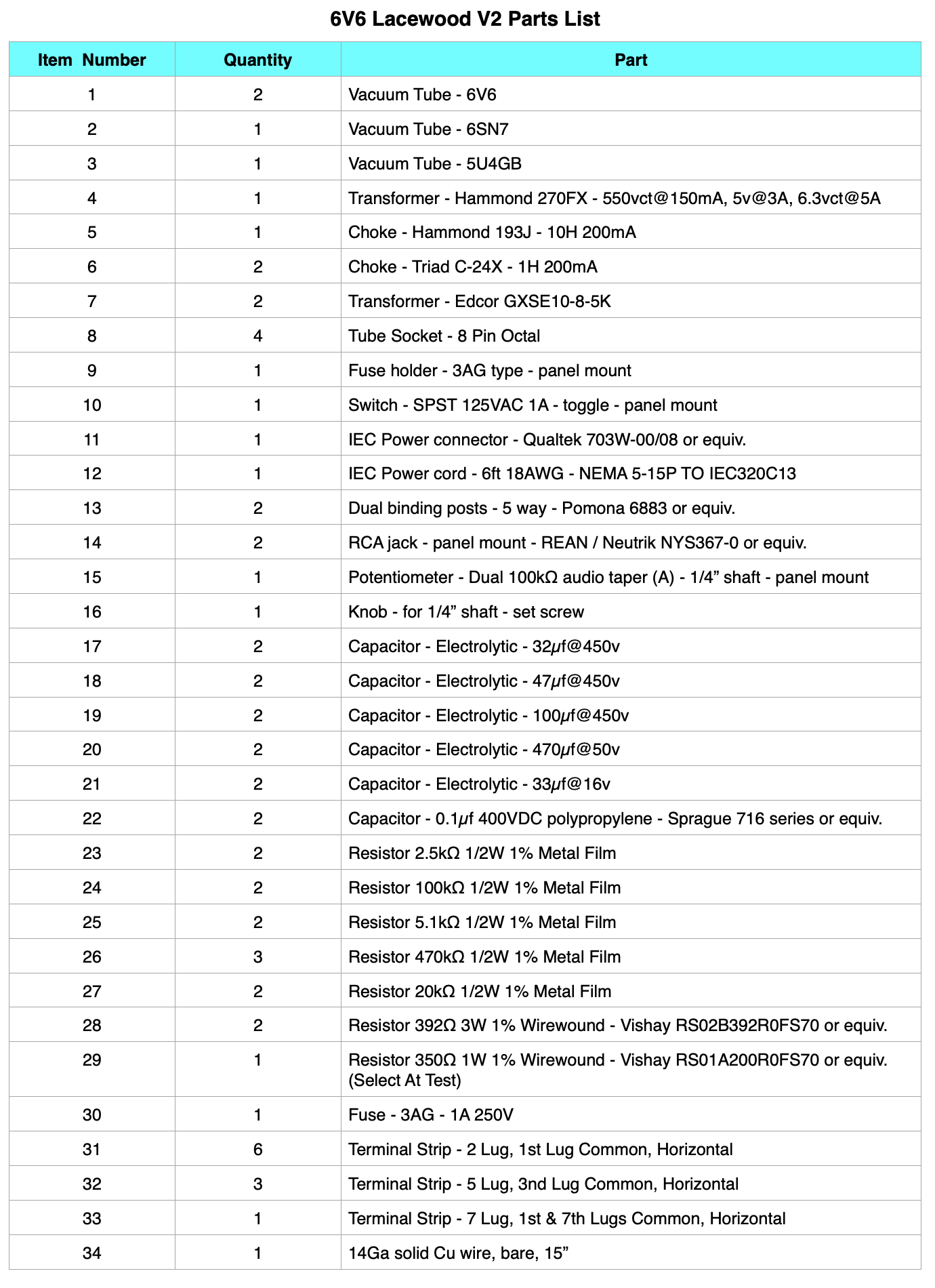
Here is the direct link: https://www.cascadetubes.com/wp/wp-content/uploads/2023/10/6V6-Lacewood-V2-Parts-List.png
Thanks!
What speakers do you run on this amp? Or what speakers are optimal for this amp. I am working on a similar design and am thinking of a pair of 8 inch celestion with 94db sensitivity.
The thing to remember with these small tube amps is high efficiency and nice lightweight responsive cones. I would recommend a full range driver something like the Fostex FE166NV in either a bass reflex or a back loaded horn enclosure. If you decide to go with a two way speaker set, make sure that the speakers are both high efficiency and the crossover is kept simple and high quality.
Hi Matt, looking forward to building the Lacewood V2 for some high efficiency speakers and would also like to incorporate a headphone output (32 ohm).
Any suggestions for the added configuration would be appreciated.
Thanks.
I’m not a real fan of integrated headphone outputs in tube amps. They tend to cause issues.
However, one of the simplest methods is to simply load the output transformers with restive loads equivalent to the speaker impedance, then just parallel load the headphones across these resistors. This usually requires a selector switch to go from speakers to headphones.
However, the solution that I really recommend for headphones is here.
Thanks, will try that and save up to build the dedicated next!
Matt, just finished my amp (first of many to come) and can’t thank you enough for the detail and help you provided. It sounds WAY better than I expected and can’t believe it also drives my KEF LF50’s cleanly and to a pretty good level.
I’m glad you like your new amp. And I am glad I could help.
I got Tango H-5S transfomers who have 32 ohm taps, they cost me around 550 usd shipped from Japan to Canada. An other solution is to use Stax headphones with the adapter.
Hello from Brazil! Excellent project. Thank you to share it. I recently bought items to build a 5e3 Fender guitar amplifier. However, I`m now interested to change to build this project. So, I have some doubts: I intend to use with Audio technical Turntable with 150mv line output (https://www.audio-technica.com/cms/turntables/7d6199a73a837511/index.html). Do you think that output is enough? Do you think the 5y3 tube rectifier is suitable for this project? And last: I have also one 12ax7 and one 12ay7 (Fender 5e3 project). Is it possible to use one of them (maybe 12ay7) in place of 6SL7? Any suggestions with this modification?
The Lacewood V2 design requires about 700mV RMS to drive the amp to full power. The turntable specification of 150mV is about 13dB below that. I would think that a preamp would be required. It is also not clear as to whether the turntable contains an RIAA preamp for frequency equalization. This is something you should probably investigate.
As for the 5Y3 rectifier; yes, it can be used in this design. However the B+ will be somewhat lower (≈20v) and amp performance will not be as good. I do recommend staying with the 5U4GB.
The 6SN7 is biased for an amplification of about 16 v/v. Using a 12AX7 (µ≈100) or a 12AT7 (µ≈60) would require a pad to control the drive level to the power stage. I would not recommend it.
Thank you for your quick reply. =)
Hello Matt! what are the specifications of the output transformers. so that I can have it manufactured? thank you !!
Primary Impedance : 5kΩ
Load Impedance : 8Ω
Primary to secondary turns ratio : 25:1
Primary inductance not to exceed : 10H
Primary resistance not to exceed : 250Ω
Core gapped for primary DC current of : 90mA
Frequency response (-3dB) : 40Hz to 18kHz
The transformers used are Edcor GXSE10-5K. However, the Hammond 125DSE can be used with good results as can the Sowter SA02.
Matt,
I am working on the 4S universal pre amp and want the Lacewood V2 amp to be my next project, I have an Encore XPWR224-120 power transformer (270-0-270) @ 125mA, could I make this work in the Lacewood V2 even though it is slightly lower voltage and amperage than you specify. Also I have tried to do some research on the 6v6 tube and most of what I find is regarding guitar amps, do you have an opinion on which 6v6 tubes are best for hifi
As you can probably tell I am a total novice but trying hard, I think you have an outstanding web site and have done a fantastic service to the DIY community.
Regards, John O.
The XPWR224 will work for the Lacewood V2 with a couple of stipulations. The high voltage winding is fine. The rewire required a 350Ω 5W resistor in the power supply to get the voltage down to where I wanted it. Your resistor will likely be different.
However, the XPWR224 only has a 2A 5V winding. This means that you will be restricted to using the GZ34/5AR4 high voltage rectifier. This is really not much of an issue as the GZ34 has lower loss which will likely offset the slightly lower HV secondary voltage. So overall, you should be fine with the power transformer you have.
As for the 6V6s, start with a pair of brand new JJs. After you get a feel for the amp you can try others if you like. Personally, I have a pair of NOS Russian 6P6S tubes that I really like for their laid back sound. SO once the amp is built, don’t be afraid to experiment a bit.
Hello, I am enjoying your website. I am a newbie at this and I would like to build a tube amp or preamp. What do you recommend as a place to start? I have experience soldering and very basic knowledge of electronics. Is there a good book to read that can go over the concepts? Do you know of a good kit with pretty detailed instructions to get me going? I particularly like the Lacewood amp and the universal pre-amp. Thanks.
The best book for new vacuum tube enthusiasts is actually a guitar preamp book: “Guitar Amplifier Preamps” by Richard Kuehnel.It is straightforward and gets to the meat of preamp design without the foolishness of Morgan Jones or the in-depth mathematics of Herbert Reich. Although, Reich’s “Theory and Application of Electron Tubes” IS the definitive introductory text on vacuum tube design. (Warning: 37MB file Theory and Applications of Electron Tubes
Kits are an expensive option but if you’re really interested, I suggest one of the OddWatt kits. They are straight forward and produce very good results.
Hey Matt. You did an amazing job for your tube amps. They look amazing. I am currently taking Electronics Engineering Technology at a post secondary. I am in my last semester and have to do a final project. I am kicking it old school and making a home theater system featuring a tube amp. Your design is amazing. I am going to use 6L6s and a 12AX7. I am also going to be using two Hammond 1628SEA output transformers. Is there anything that I should look out for? Thank you so much for showing your design process and great job.
Cheers
Anthony N
When you go through your design process make sure the design you use has a well though out philosophy. If you are using the 6L6s in SE, then the bias will likely be relatively low (≈15-25v). The 12AX7 is likely to give you a lot of gain so your amp will be VERY sensitive. Is this a requirement due to low input signals? I’m curious.
Hey Matt. Thanks for the reply. The sensitivity is preferred. I have some gear that doesn’t output much as well as other gear that outputs more. Having the flexibility would be better. The range would be from approximately 200mVrms to 2Vrms. Thanks again for all your help.
Cheers
Anthony N.
Hi Matt,
Maybe a real novice question, I don’t know. All of my builds of your amps work and sound beautiful but, I can never achieve absolutely no noise when a player is connected but music paused. At full volume I can hear a slight hum or buzz. It is never audible when music is playing even at very low volume. I’ve tried many different layouts and have moved signal leads whilst listening to no avail. I’ve asked the question here because the lacewood V2. is what I’m using now, I had exactly the same with the 6EM7. My question is.. Does 50Hz instead of 60Hz mains supply make a difference to the PSU design? I’ve read your article on PSU design, but I’m afraid it is way over my head. It takes nothing away from my listening experience. I’m just curious to see if I can make my amp as quiet as yours.
Well hum and buzz are very different things. With hum I generally look for coupling and filter issues as I’ve discussed before. And the difference between 50Hz and 60Hz is really pretty minimal. But buzz is almost always due to something outside the amp. In our modern digital world, there are numerous things that can cause buzz and hiss in our audio equipment. So my first recommendation is this: a change of venue. Try taking an amp to a friend’s house or just to another room even. Does the buzz or hiss change? Can you turn off lights or computers and make it change. You really have to think like a detective. What’s different? Can you induce a change in the sound? Some CFL and LED lighting can generate horrible fields. Sometimes the high frequency noise comes in on the mains themselves. And some modern power equipment actually communicates status via high frequency signals on the power lines. Also look at your sources. Maybe the noise is there. I had a headphone amplifier at work hooked up to my computer’s sound card. It gave me no end of trouble with hiss and buzz until I tried it with an iPod. Then it was quiet as a church mouse.
I’m sorry I can’t offer any more concrete suggestions. The problem is that every situation is unique. Since this is something that crosses multiple projects, I would suggest you start looking for whats common. Good Luck.
Thanks for quick reply. Will look at all options.
Hi Matt, I built the original Lacewood amp 18 months or so ago, and have enjoyed it almost daily. I found this new build interesting and decided to build it almost exactly as you have described in this article. Just a few changes in resistor values when I didn’t have the one’s in the design.
All seemed to go well, but when I powered it up, the B+ went up to over 300V, then fell to 215V as it warmed up. Iv’e been over it numerous times, but can’t see where I made any mistake or difference in wiring from your design. Pulling either output tube allows the B+ to rise to 279V and pulling just the driver it rises to 226V.
With no input, output tube voltages are – plate 210, and cathode 10.5. On the driver tube, plate 71 and cathode 2.6. PS voltages are 215 and 188.
I’m at a loss as to what to do next, and wonder if you have any suggestions. Appreciate any help you can give.
First, don’t worry about initial high B+, this is normal behavior. It’s the steady state values that seem low.
The behavior you describe in removing one or two power tubes is indicating that you are experiencing a large voltage drop somewhere. The 64V rise when removing 42mA would indicate an equivalent loss resistance of about 1.5kΩ. This is significant. I suspect a bad rectifier.
The first filter cap after the rectifier should be charging to around 340V at steady state. At ≈89mA total draw the 350Ω resistor should be dropping about 31v. The Hammond 193J has an internal resistance of about 82Ω giving another 7.3V of drop. So the second filter cap should be about 38v to 39v lower than the first at steady state. The 24-X chokes have an internal resistance of 50Ω that should be dropping about 2V. Here are the steady state voltages I measured for my amp build.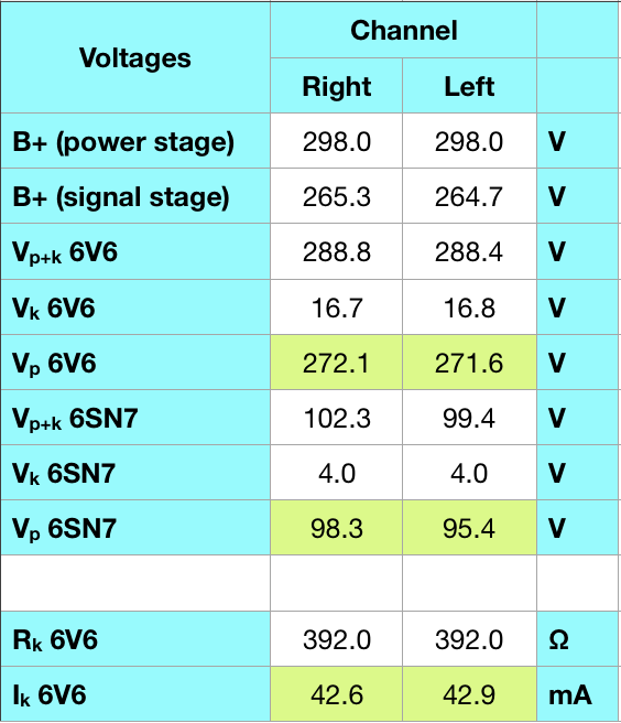 Since your final voltage is low the first thing to do is to determine what are the up front voltages and current levels. It may just be a bad rectifier, or a miss-marked component. Check your voltages and get back to me.
Well, I found the problem, though I don’t really understand it. Comparing the picture of your wiring to mine, I see the H V winding center tap is connected to the gnd post of the 32uf cap, whereas mine was connected to a gnd at a terminal strip for the power cord. I changed that gnd to the filter cap, and the voltage to the 6V6’s is now 280. What a difference! The amp sounds wonderful. I’m glad I made I made this conversion. But I am curious, why would the position of that ground make a difference like that? Anyway, thanks for your detailed reply, and congratulations on a really nice build.
Ron
It depends on your ground scheme. But I suspect a high resistance between chassis ground and signal ground was the culprit.
Hola Matt, La inquietud de RON es interesante, yo estoy empezando a construir éste amplificador, en Junio tendré todos los componentes y estoy ansioso por comenzar.
Al momento de terminar y encender el interruptor debo probar, si antes no hay algún fuego 🔥 por apagar, los voltajes en los puntos críticos, uno por uno hasta estar seguro que está listo para recibir la señal de audio entonces me doy cuenta que no los tengo por lo que te pediría el favor de que los incluyas en el diagrama.
Saludos.
>Hi Matt, RON’s concern is interesting, I am starting to build this amp,
>in June I will have all the components and I am eager to start.
>At the time of finishing and turning on the switch I must test,
>if there is no fire 🔥 to turn off, the voltages at the critical points,
>one by one until I am sure that it is ready to receive the audio signal,
>then I realize that I do not I have so I would ask you to please include
>them in the diagram.
>Greetings.
Alexis; I have attached a schematic with the voltages. I hope this helps. Let me know if you have any other questions.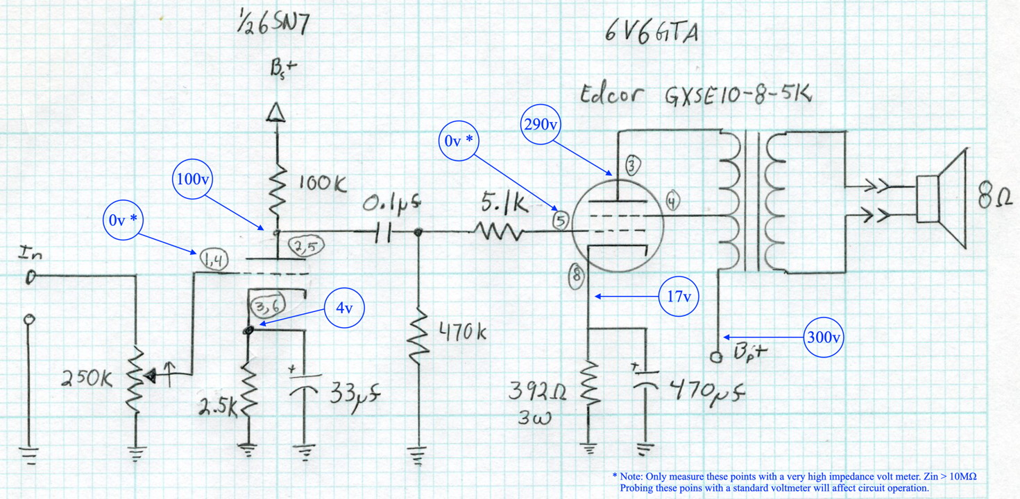
Note that these voltages are approximate. Any value within about 10% is probably more than acceptable.
Hola Matt, muchas gracias por la información de los voltajes en los puntos críticos del circuito.
Tengo casi terminado el circuito del Lacewood 2.0/UL.
Todas las resistencias y condensadores distribuidas en orden y sub-grupos según el número de pin de cada tubo esto lo hice en una placa PCB sin cobre y utilizando torretas para soldar los componentes.
Ahora debo hacer los transformadores para lo cual ya tengo los materiales necesarios ya que ésto lo aprendí en mi anterior trabajo como Profesor de Educación Técnica.
Como el transformador de salida del 6V6 es Ultralineal te pido por favor me indiques el % para la derivación iniciando a contar las espiras desde el punto B+.
También te solicito tu opinión acerca de la utilización de dos diodos de estado sólido atados a las placas del tubo rectificador para formar el puente de Graetz ya que ésto me permitirá el devanado de alto voltaje de un solo valor y sin punto medio.
Sin más por ahora y agradeciendo tu valioso aporte a todos los que seguimos tu página web.
>Hi Matt, thank you very much for the information on the voltages
>at the critical points of the circuit.
>I have almost finished the circuit of the Lacewood 2.0 / UL.
>All the resistors and capacitors distributed in order and
>sub-groups according to the pin number of each tube I did this on
>a PCB without copper and using turrets to solder the components.
>Now I have to make the transformers for which I already have
>the necessary materials since I learned this in my previous
>job as a Technical Education Teacher.
>As the 6V6 output transformer is Ultralinear, I ask you to
>please indicate the% for the derivation, starting to count
>the turns from point B +.
>I also ask your opinion about using two solid state diodes
>tied to the rectifier tube plates to form the Graetz bridge
>as this will allow me to wind high voltage single value and
>no midpoint.
>Without further ado for now and thanking all of us who follow
>your website for your valuable contribution.
Alexis; Glad things are progressing. The output transformers I use are all 40% UL.
As to building a complete full wave bridge using by combining diodes and the tube rectifier, I recommend against it. You can make it work but the bridge is badly unbalanced and the ripple is asymmetric and significantly higher. Usually I recommend sticking to either a center tapped secondary with vacuum tube rectification or a single secondary with four solid state diodes. If you decide to use solid state diodes, be sure to use fast recovery diodes to minimize noise.
Hi Matt:
I liked your detailed optimization study.
I took what you did and built my smaller version with some circuit changes in bias using a CCS @46ma and a 12SL7 because I required more gain as I feed from Mp3.
I also simplified the power supply and filaments to gain space in my little wood box chassis.
http://www.diyaudio.com/forums/tubes-valves/322846-12sl7-6v6-se-amp-ver-lacewood.html
( http://pbpix.com/amp/se%2012sl7%206v6%20toroid%20final%20may%2014th%20'18.png )
Nice build. I’m glad you could draw some inspiration from this project.
Hi again Matt. I am inspired to try and construct one of these having listened to my friend’s quad 22 / 2’s? in my misspent youth. Alas I am a novice and am wary of the high voltages so if I do go ahead I would need to find someone to help check progress if that is indeed possible. I was trying to work out the values of the resistors and caps not evident on the schematic ie the wattages, precision etc as the colours and any numbers are a bit hard to see on the pics. Do you have any general information or guidelines how you have approached this? Much appreciated.
I do have some general guidelines for components.
For resistors I use 1/2W, 1%, metal film resistors. If they need to dissipate more than 1/2W, I tend to use wire-wound resistors of the highest precision I can get.
Capacitors are chosen by application. In power supplies I use capacitors rated at voltages at least 1.4 times the transformer unloaded half-secondary voltage. This assures they are within tolerance even if the amp is not drawing current. The big JJ can capacitors are rated at 500v and the power stage filter caps are rated at 450v. This approach goes for coupling capacitor voltages as well. The ones I used are actually rated at 630v but this is overkill; 450v would have been more than sufficient. Bypass capacitors are just rated at something over the bias voltage. For signal stages this is usually just a few volts so 16v or 25v caps work well and are relatively small. In power stages, it depends on the eventual bias voltage. In this amp, the 6V6 bypass capacitors are rated at 50, but 25v would have been acceptable as well.
Does this help?
Yes thanks Matt.
Hi Matt and thanks for making this design available. A few years ago I built a 6N1P/KT88 SET via schematics on the internet, paired it with Klipsch HE speakers, and subsequently shelved my solid state Yamaha (great specs but I am now in love with “glass”).
I plan to build your Lacewood V2, and would be interested in your perspectives on KT88 versus the 6V6.
Thanks much.
\Mike R
Nice lookin’ FFT! The harmonics are right down there with real world transistor amps. On my homebuilts, the second and third are about equal height, and a few tiny higher odd order blips. Your amp measures a lot better than a lot of “boutique” tube amps that I have seen. Some well respeced SET’s seem to produce a full spectrum of harmonics, your UL is really clean.
Finally – gotta love them Rigols – never saw so much bang for the buck! (Mine is an older model, but still can’t believe all that it can do!)